| Home | Open Account | Help | 292 users online |
|
Member Login
Discussion
Media SharingHostingLibrarySite Info |
Steam & Excursion > El Paso Tx 1938Date: 09/26/16 13:25 El Paso Tx 1938 Author: tomstp A bright sunny day greets Texas & Pacific class P1a 4-6-2 # 711 the power for T&P's" Texas Ranger " in the open air platforms of El Paso's SP station. Note the sign complete with T&P's diamond herald just in front of the engine. The sign would be changed out for each of T&P's passenger trains giving their names..
711's looks would be greatly altered by 1940 when dual air pumps and shields would adorn the pilot and a Elesco feedwater heater would also be added along with boxpok main driver, all to increase steaming and speed. In addition it would also receive a larger tender. from one of the roads baldwin 2-10-2's. Edited 6 time(s). Last edit at 09/26/16 13:33 by tomstp. 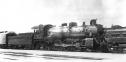 Date: 09/26/16 13:34 Re: El Paso Tx 1938 Author: tomstp Sorry for all the edits. Kept trying to get the picture a little better.
Date: 09/26/16 16:20 Re: El Paso Tx 1938 Author: Bob3985 A good looking Pacific Tom, thanks.
Bob Krieger Cheyenne, WY Date: 09/27/16 01:30 Re: El Paso Tx 1938 Author: Cjcheely Awesome photo.
FYI, its at El paso union depot at one time it served the following railroads Southern pacific EP&SW Santa fe Texas and pacific N de m This is also pre trainway Posted from Android Edited 1 time(s). Last edit at 09/27/16 01:33 by Cjcheely. Date: 09/27/16 02:19 Re: El Paso Tx 1938 Author: MMD Interesting, both Injectors are on the Engineers side I would have though at least one would have been in the control of the fireman.
Malcolm New Zealand. Date: 09/27/16 06:52 Re: El Paso Tx 1938 Author: tomstp Malcomb. There is only one injector on the engineer side. Note the line you are speaking about does not have a check valve. I am not certain what it is but, I believe it is a Nathan type DV-2 force feed lubricator. In pictures I have, that line appears on all P-1a class engines delivered from Baldwin. It does not appear on the other two classes and diagram sheets listing lubricators on other classes do no have that force feed lubricator.
Others more knowledgeable about steam engines may be able to shed more light on the subject and I certainly would not mind being corrected. So, if someone kows exactly what it is, let's hear from them. Date: 09/27/16 19:42 Re: El Paso Tx 1938 Author: MMD Tom I've gone back and had a good look at the photo and what I took for the injector in front of the cab is in fact the 'starting valve' for the non lifting injector under the cab on the engineers side. The pipe that runs along the boiler above the injector delivery pipe seem to terminate at the very front of the boiler barrel, I dought it's a Lubricator line it's to big for that so like you I am wondering just what it is.
Malcolm New Zealand. Date: 09/28/16 06:49 Re: El Paso Tx 1938 Author: tomstp Wes Camp can you identify what the pipe is?
Date: 09/29/16 16:30 Re: El Paso Tx 1938 Author: wcamp1472 Just a WAG, here....
The two supports along the ( sliding?) shaft, and what appears to be the clevised-end of a lever under the jacket, has me thinking that it is an early form of a front-end throttle..... It looks like it may operate a throttle valve, in the drypipe at the entrance to the superheater header, rather than the later common practice of having the mutiple-poppet valve arrangement of later front-end throttle designs, where the throttle valves are downstream of the superheater units... I suspect that this throttle valve, proper, might use a small 'pilot valve' and a single, central 'balancing chamber' ( to offset the pressure of the steam-closed throttle valve.. And make the throttle open more easily). If a 'photoshop' guy could enlarge the pic & and that area at the front of the rod & clevis, it would help.. W. Date: 09/29/16 20:15 Re: El Paso Tx 1938 Author: MMD Wes I think the the pipe / rod it too 'low down' on the boiler barrel to be an early front end throttle as it would be below the level of the water in the boiler.
I sure would like to know just what it is. Malcolm New Zealand Date: 09/30/16 15:59 Re: El Paso Tx 1938 Author: wcamp1472 Malcolm,
Thanks for your comments.... There are several factors at work here... This modification predates the 'modern' combined multiple (poppet) valve throttle body/superheater header casting later pproduced by ELESCO, the loco component vendor of the era.... I am speculating here, but it looks like the throttle valve assembly in the smokebox is 'upstream' from the possibly' early version' of a superheater header. Early in the development of single-element, lifting throttle valves ( necessitated by the development of the successful Schmidt superheaters,) ---- they are held closed by boiler pressure. Typically, they have open pipe/piston diameters in the 8-inch to 10-inch range. Also, typical boiler pressures for locos like this, were in the 200 psi to 225 psi region....thus, without a piston "pressure-balancing" method, an engineer could never achieve the strength to open the throttle, against full boiler pressure.... [ Area of a disk, in inches, is equal to pi times the radius squared, ----- now, multiply the number of square inches of area of such a piston, and multiply by the pounds per sq. inch....you'll see that it is thousands of pounds, across the entire valve face...holding the valve solidly closed....] So, early, single 'plug' throttles were fitted with a central 'balancing chamber' and a small-area "pilot valve" that fills the balancing chamber with steam pressure. The pilot valve's small diameter allows the engineer to raise it a fraction of an inch, thus allowing boiler steam on both sides of the trrottle valve, further raising of the throttle is now posdible, aided by the 'balanced' piston. The balance area below the main valve is always a little less than the major diameter --- thus, there is always more pressure for closing the valve, than for opening. It is 'biased' with a closing force, for safety reasons.... It had been common for a rather tall, 'balanced' throttle, to have been mounted up, inside the steam dome, proper. The valve, itself, would have sat on top of the drypipe elbow, and it's operating levers would have had it arranged to drop to the level of the lateral linkage to the throttle quadrant (in the cab) was in-line with the bottom of the forward drypipe extension, through the front flue sheet. I am presuming that this was an attempt to move the balanced-piston throttle into the smokebox.....such an arrangement, formerly inside the steam dome, typically has a 'yoke' arrangement over the top of the main operating throttle valve so that it lifts evenly, without binding. Such an improvised arrangement utilizes the typical throttle linkage that would have been mounted in the dome. Here, the designers were faced with a typically tall throttle assembly, crammed into the smokebox. In the photo, I presume that we are seeing only the outer bell-crank and the rod clevis....the rest of the linkage is inside the smokebox. There are undoubtedly several more levers and cranks linking the rotating shaft to the operating valve, than we can see. We most resort to our imaginations It took many years and trials before the modern, multiple-poppet front end throttles and superheater headers were perfected and assumed a common design. Next, it is probable that the modified dry pipe, inside the boiler, was fitted with a 90-degree elbow, at the bottom of the steam dome (replacing the former 'throttle stand' assembly). The replacement elbow would have had a vertical extension, that rose very close to the underside of the steam dome cover. The aim here, of course, is to take boiler steam from the very top of the boiler, at its highest point to prevent, 'priming', or sucking liquid water into the steam delivery pipes to the units and the cylinders. In the above assumption, the discussion about the relative water level in the boiler and the position of the throttle operating reach-rod, is moot. The steam, on its way to the superheater units, via the throttle, is the greatest degree of 'dry steam' ( free of moisture droplets) that can be derived from the dimensional limits of the boilers of that era. This application is an excellent illustration of different railroads' master mechanics, boilermakers, and builders to try to apply improvements in these 'one-offs' fashion. It is marvelously indicative of the ingenuity and design crafts of that inventive era. There are many similar efforts across the spectrum of remaining examples, worldwide, the the inventive genius of theses heroic problem solvers. One of my favorites of ingenuity is the famous Beyer-Garrat design(s) of locos...they are really marvelous, in my opinion. Again, thank you for your comments and your interest.... i remain immensly curious about all the different problems that our predecessors tried to solve, their successes and their failures. This is a particularly interesting variant.... "Keep those cards and letters coming, folks...." Wes Camp Edited 2 time(s). Last edit at 09/30/16 16:06 by wcamp1472. |