| Home | Open Account | Help | 289 users online |
|
Member Login
Discussion
Media SharingHostingLibrarySite Info |
Steam & Excursion > Siderods on N&W 4-8-4s?Date: 07/18/17 11:03 Siderods on N&W 4-8-4s? Author: timz 1957 pic of N&W 604
https://www.trainorders.com/discussion/read.php?11,4340528 shows the original siderod layout, with two siderods each side between the second and third driver axles. Why hasn't the 604 had its second rod removed? Surely that modification didn't start later than 1957? So only some 4-8-4s got it? (Pics of the modification https://www.trainorders.com/discussion/read.php?10,4236419,page=1 Edited 1 time(s). Last edit at 07/18/17 11:05 by timz. Date: 07/18/17 15:55 Re: Siderods on N&W 4-8-4s? Author: wcamp1472 Surely, the modification involved MORE than simply removing the siderod.
The original intent of the siderod modification was to reduce the mass of the whirling driver counter weights... On the smallish drivers, the 'moment: of inertial( the smaller the driver diameter, the more mass must be added to achieve the desired amount of partial counter-balance) requires that the counter weights be substantially increased --- compared to a much larger driver diameter, say 80". Larger drivers, allow less massive counterweight mass, account of the higher rim velocity. The Mechanical Advantage of the weights being much farther from the axle center allows the 80" drivers to use a LOT less mass in the counter weights. The whirling mass of the smaller drivers means that the large centrifugal force, in effect for 360 degrees of rotation.. BUT, the reversing-mass of the reciprocating (back & forth motion) drive rods and pistons only occurs at the ends of the piston strokes ---- and intent of the counter weights is to use the opposing centrifugal force of the whirling weights to 'offset' the masses of the reversing pistons, twice each revolution....at each cylinder head. The reversing of the pistons only occurs at the front and back of the cylinders --- we'll call the front dead-center, the "3 o'clock" position. and the rear dead-center, the "9 o'clock" position... The consistent mass of the whirling weights is NOT counterbalanced ( by the side rods being changed in direction) at the TOPS of the crank circle (12 o'clock), and also, NOT counter balanced at the BOTTOMS of the crank circles.... (the "6 o'cock" position..). NOW, at 110 MPH, the drivers are whirling well over 350 RPMs... that force LIFTS the drivers OFF THE RAILS, against the force of the springs, ----thru the '12 o'clock' arc of the drivers. AND, conversely, the drivers are smashed into the rail head, through the '6 o'clock', BOTTOM arc ... only now, the springs have rebounded and additionally drive the massive counterweights --- with greater force---- into the rail head. Its a terrible ride and ruins the rails, every crank interval...for miles !! The N&W had to reduce the mass of the counterweights on all 8 drivers,,, they had to design all new patterns and cast all new drivers to accomplish that mission: Lighter Weights. Molten lead is poured into the voids of the crescent-shaped counter weights cast into each driver.... The backs of the void space in the counterweight casting is filled with lead and then, steel plates are welded over the void cavities..... Over time, the lead casting turns into a white powder in the voids ( continuous pounding). You cannot simply pour-in less lead into a vastly oversized void. New drivers necessarily involve smaller counterweights. NOW.... having met the goal of reducing the massive counterweights, gives you the opportunity to reduce the corresponding masses in the pistons and drive rods. The Timken Tandem Rod arrangement, has the main rod fitted between the two 'tandem rods'. The tandem rods connect the crank pins of driver No. 2 to driver No. 3 ---- driver No. 4's siderod is fitted between the back ends of the two Tandem Rods....at the No. 3 crankpin.. Driver No.1's siderod, located next to the driver Hub of drivers 1 & 2; (the inner tandem rod is the next rod, out from the hub). The N&W design staff sought to remove the tandem rod arrangement, thus reducing the reciprocating mass, and allowing for lighter siderods. HOWEVER.... the missing tandem rods, meant that the NO. 2, 3 & 4 crank pins were WAY too long, and were far away from the driver hubs... The solution? Why shorten crankpins, of course... But, that means entirely new, shorter, crankpins for new improved weight savings.. They're making progress towards their goal of great weight savings.. Each end of the Timken side rods contains a complete Timken roller assembly AND its surrounding brass bushing...that also involves: the inner race ( the 'cone'), the individual rollers (Cylindrical), the roller 'cage', the outer race ( the 'cup'). All those separate R/B pieces are in each lobe of the two-ended siderods. So, by eliminating a Tandem Rod, Roanoke achieved a significant weight saving advantage. Elimination of the outer tandem rods, was achieved with: all new driver castings, all new crankpins, and new rods for connecting No. 3 driver to No.4. Also, a whole new mainrod had to be designed and forged to effectively harness the pistons' thrusts ... that yielded 80,000 pounds rated tractive effort... The existing Timken 'lightweight pistons" and their hollow piston rods, together with lighter crossheads, all contributed to a considerable rotating weight savings. In three or four years, the Js were replaced by the dismals....giving new meaning to "The Dismal Swamp" !!!! The 'Boys in Roanoke' had achieved their goal of lighter counterweights, lighter reciprocating masses, and higher track speeds...and minimized 'dynamic augment', and eliminated the kinked and battered rail problems.... All to be enjoyed at today's screaming 40 MPH!! The 80" drivered engines, like the Santa Fe's 2900s are wonderful examples of Timken's art... but, the larger drivers simply mean a smaller weight--less mass--- slung at high speeds, produces the same amount of 'counterbalance effect': ----- but, the counterweight's 'inertia moment', is moved farther away from the driver centers --- compared to the tiny drivers of the J. A smaller mass, at high rotative speed, produces the same benefit as heavier, closer in weights... Years ago, I had an argument with a noted steam authority about the (hypothetically) FASTEST engine in North America.. He argued that it was the J! So I said: "assuming that you took the J to its absolutely Fastest driver RPMS and then take a competing engine (that had to beat) that RPM to win...." I said: "I'll take any 80"-drivered counterpart, run it up to the same RPMs as the J, and I'll easily cruise on-by you RPM for RPM..!" ( wouldn't you agree?) [ a larger diameter driver at the same RPM will, by definition, cover greater distance, in the same amount of time] BUT still, if I took the 80" drivered engine to IT'S 'maximum permissible RPM', then I'd really be flying. No wonder a Poppet valve PRR T-1 did 140 MPH.... Sorry, guys ---- I'll take 79" & 80" driver engines, any day... Move over J, you're about "to be served.." W. Edited 6 time(s). Last edit at 07/18/17 17:06 by wcamp1472. Date: 07/18/17 17:56 Re: Siderods on N&W 4-8-4s? Author: CPRR Jesus Wes, you really need to either write a book, or conduct classes in steam locomotion. I would buy or go to either one.
Is a Simplex with a one large driver even faster, assuming a straight track? Posted from iPhone Date: 07/18/17 19:09 Re: Siderods on N&W 4-8-4s? Author: wcamp1472 Thank you...
For a good comparison...go to the second link that timz has included in hi post, above. Look closely at the comparisons of the sizes of the counterweights, between the two styles, It looks like that revised design is easily half the mass of the earlier version.... The lighter counterweights are very elegant, I am continually impressed by the engineering thus demonstrated, by the N&W engineering and fabrication folks. Thank you, Scott Lindsay, for your efforts at restoring and preserving the 611. We are deeply indebted to your continued efforts. Wes. Date: 07/18/17 19:14 Re: Siderods on N&W 4-8-4s? Author: Margaret_SP_fan Wes --
What about an 84-inch-drivered Milwaukee Road Hudson??? A now-deceased steam-era Milw fireman said his "personal best" with one of those F-7s was 127.6 mph!! (Also said it took 15 MILES to get up to that speed.) What say you? And I agree with CPRR -- you have GOT to write a book! I'd buy it in a heartbeat! (And please give classes, too!) Did the T-1 really go 140??? When? Where? Wow....... Date: 07/18/17 19:15 Re: Siderods on N&W 4-8-4s? Author: wcamp1472 " Is a Simplex with a one large driver even faster,
> assuming a straight track? " I'd look to the MILW Class A, 4-4-2 Hiawatha locomotives...they also were real screamers... Not the STRONG BEAST the J class is, but very speedy, simple and beautifully engineered. W. Date: 07/19/17 07:30 Re: Siderods on N&W 4-8-4s? Author: johnacraft timz Wrote:
------------------------------------------------------- > 1957 pic of N&W 604 shows the original siderod layout, with > two siderods each side between the second and third driver axles. > Why hasn't the 604 had its second rod removed? > Surely that modification didn't start later than 1957? So only > some 4-8-4s got it? 611's 1950 builder's photo shows the original Timken arrangement, so it's a safe assumption that the redesign is post-1950. The PRR tests of N&W 610 were in December 1944 and January 1945, so almost certainly with the original rod design. (610 is shown in this 1956 photo with what appears to be the original rod design: https://goo.gl/iMM5r8 ) There is nothing about the new rod design in Jeffries' "N&W: Giant of Steam." That book is pretty comprehensive, and goes into great detail about engineering upgrades in the modern steam classes. That may be a clue that the redesign wasn't considered particularly important. My first guess was that the first order (which were built with multiple bearing crossheads) might have somehow been different. But this photo of 608 with the original rod design in 1958 makes that implausible: https://www.flickr.com/photos/130647200@N05/34626226411/in/album-72157669851188905/ My next guess was that 611 got the new rod design when being repaired after the January 1956 derailment at Cedar, but this photo appears to show 611 with the original rod design in November 1956: https://goo.gl/kWRxHQ Summarizing the photos I was able to see the rods clearly enough, more locomotives had their original rod design in the 1956-1958 period (600, 603, 604, 608, 610) than had the modified design. I found only one other J that appears to have the new design, of 605 in 1955: https://goo.gl/Wpo7VW So I think it's safe to say this modification wasn't widely applied. It's particularly interesting to me that 605 may have had the new rods in 1955, but that 611 didn't get them when being rebuilt after the wreck. Edited 1 time(s). Last edit at 07/20/17 08:13 by johnacraft. Date: 07/20/17 04:37 Re: Siderods on N&W 4-8-4s? Author: SR-RL_Nr_10 A bit late to the thread but as the guy with the spreadsheet, attached is a table with driver size and the RPM resulting from various speeds (not posted inline because the BB software makes a hash of tables!). Numbers are rounded to whole digits because of variables in driver size because of wear. No opinion is offered to whether an engine design could actually achieve the 140 MPH speed. But the calculated RPM makes the engineering solution very difficult. Remember that when steam engines were designed, all the balance calculation were done by a person sitting at a desk. Baldwin messed up at least two classes of engines dynamic balance calculations, the Atlantic Coast R-1, 4-8-4s and the New Haven I-5 Class 4-6-4s. Both classes required extensive rebuilding to reach railroad required speeds. So when the Js were calculated to be able to reach 140 MPH without track damage, I have some skepticism until proven otherwise.
One of the interesting facts is the old adage that a locomotive's best speed is the speed at which the speed in MPH and the driver size in inches is equal does have some utility. When speed in MPH and driver size in inches are equal, the drivers are always going 336 RPM. I did find a reference that not all "J"s had the side rods reduced from two to one. The information is in the Wiki entry in the second paragraph under "Design": https://en.wikipedia.org/wiki/Norfolk_and_Western_Railway_class_J_(1941) But when I checked the reference listed in the Wikipedia article, it didn't say anything at all about the modification. Just another demonstration that Wikipedia is not always a reliable source. Edited 3 time(s). Last edit at 07/20/17 04:50 by SR-RL_Nr_10. 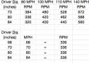 Date: 07/20/17 16:55 Re: Siderods on N&W 4-8-4s? Author: elueck Just remember that 600 RPM is 10 revolutions per second.
Posted from Android Date: 07/20/17 18:30 Re: Siderods on N&W 4-8-4s? Author: agentatascadero Just wondering if there is a generally accepted maximum driver wheel RPM....or maybe two.....maximum possible, unlimited version, and maximum possible in regular service?
AA Stanford White Carmel Valley, CA Date: 07/20/17 19:08 Re: Siderods on N&W 4-8-4s? Author: SR-RL_Nr_10 Having run the RPM calculation on a bunch of engines for which I had some idea of their operating (time table) speed, I've generally seen three very approximate RPM limited speeds. The first is "drag" freight, how much an engine can pull limited by tractive effort and the coefficient of adhesion. "Time" freights which operated pretty much at the 336 RPM speed range. This one is a bit harder to see because the many engines with 56 to 63 inch drivers were limited to about 50 mph because of the inability to counter balance the smaller driver for a higher RPM. So they fall below the "speed as defined by driver diameter" speed. I've included the calculated speed for the small drivers for comparison, but I know of almost no examples of a small driver engine exceeding the 336 RPM speed. The last RPM category is the "passenger" engine which operated at roughly 400 RPM. Flatland engines had large drivers, 79 to 84 inches, mountainous railroads operated engines in the 70 to 75 inch range. Again, this table is a generalization and there are exception and of course individual engineers did what they thought they needed to do to keep a schedule. THE Time Table was the highest authority regarding locomotive speed.
CORRECTION: I put in 68 inch drivers when I meant 63 inch drivers. 63 inch driver @ 250 RPM = 47 MPH 63 inch driver @ 336 RPM = 63 MPH 63 inch driver @ 400 RPM = 75 MPH Edited 4 time(s). Last edit at 07/20/17 21:03 by SR-RL_Nr_10. 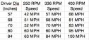 Date: 07/21/17 07:53 Re: Siderods on N&W 4-8-4s? Author: feltonhill I’d like to add some additional perspective to wcamp1472’s detailed discussion of the tandem rod setup on the N&W Class Js. This is not meant to be an exhaustive study. It‘s intended to be additional information regarding how N&W worked.
N&W converted at least four of the Class J 4-8-4's from tandem intermediate rods (between #2 and #3 driving axle) to single rods from about 1952 to 1956 (600, 605, 610, 611). How did this evolve and why did they do this? Initially, all modern 4-8-4's that were equipped with roller bearing rods using the so called tandem rod connection between #2 and #3 axles. In addition, because of this configuration, all of them had relatively long crankpins on #4 axle. The examples are: N&W Class J (1941-1950) ATSF 3776 and 2900 classes (1944 estimated) NYC S1a, S1b and S2 Niagaras (1945) C&O J3a (1948). Further, there were a few 4-8-2's that were equipped with roller bearing rods, either as-built or retrofitted. Two known examples are: NYC Mohawks (a few, probably around 1943-1944) UP 4-8-2 (one or two estimated, date unknown) Because all railroads used the same method (tandem rods), this was likely the industry standard for handling the forces that had to be distributed through the running gear, particularly between axles #2 and #3 of a 4-axle engine set. N&W revised the Class J rods to do away with the tandem rod setup on four locomotives as wcamp explained earlier in this thread. However, I believe there was a earlier link that should be considered, the N&W Class A 2-6-6-4. In 1948, N&W ordered the last five Class A’s and had them equipped with roller bearing rods. The design of these rods merits a closer look. The main rod drove on axle #3 of each engine set. Therefore, the force had to be distributed to two additional axles, the same as the 4-8-2s and 4-8-4s, except the axles were forward instead of behind the main crankpin. These rods operated in a more constricted space on the Class As than they did on the 4-8-4s, so there wasn’t room for tandem rods. N&W and Timken designed an single intermediate rod instead. There was no precedent for this because no 4-6-6-4's were equipped with roller bearing rods. This modification is visible in photos of the last five A’s. The rod hub on #2 axle is clearly larger than the rod hub on #1 axle. The design was ultimately successful because the final Class As were no slouches in the freight-moving department. I checked some drawings at the NWHS archives a few years ago and I noticed that there was some commonality between the Class A and Class J rods, particularly the single intermediate rods. However, the Class A drawings were generally dated 1948, and the Class J comments were added from about 1952 through 1956. It looks to me as if N&W took what it learned from the Class A rod design, and applied it to the Class Js. As discussed above, it would be a design improvement if the #4 crankpin could be shortened by placing the rod closer to the wheel. At a minimum, this would also improve one of the equations used to cross-balance the Js (i.e., keeping the rotating mass closer to the locomotive centerline). If there is any doubt that this application was also successful, four of the last five Class J’s retired had this rod modification. In other words, all of the modified Js lasted to the end, regardless of their construction date.. Date: 07/21/17 10:03 Re: Siderods on N&W 4-8-4s? Author: wcamp1472 Thank you, feltonhill---
I did get up close to the 1240, in June 1959, cold and dead inside the Schaeffers (?) Crossing roundhouse... She was BEAUTIFUL.... Easily my all-time Favorite Steam Loco, bar none!! I still mourn her passing... I'd give several vital body parts to have her back again ... I'd BRIBE Scott, just to let me polish them Rods.... Thanks for the endorsement of my dumbed-down write-up on the J's rods.... I'm a big admirer of N&W's brilliant engineering department. It's great to have your esteemed comments ... Wes Posted from iPhone Date: 07/21/17 12:08 Re: Siderods on N&W 4-8-4s? Author: sgriggs I found a drawing on the NWHS archive website that shows the arrangement of the J-class with the tandem rod configuration (see attached). As Feltonhill commented, the #4 crankpin is relatively long (see red circled area). Evidently, the N&W sought to reduce this offset by eliminating the tandem intermediate rod and moving the rear rod inboard to be in line with the front side rod. This change made the #4 crankpin the same as the #1 crankpin. The two other drawings are the orginal #4 crankpin arrangement (with tandem intermediate rods) and the design used on the #4 and #1 wheels with single intermediate rods. The first revisions of the drawings associated with the single rod design are dated 1952.
Scott Griggs Louisville, KY 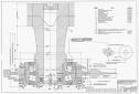 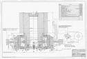 |