| Home | Open Account | Help | 305 users online |
|
Member Login
Discussion
Media SharingHostingLibrarySite Info |
Steam & Excursion > Slanted Cylinders?Date: 02/05/19 16:03 Slanted Cylinders? Author: LJGross Here's a steam engineering question. I had the opportunity to ride the footplate of New Zealand Railways Ab Class 608 in 2017. This is a little jewel of a 4-6-2 operating under the auspices of Steam, Inc. One thing I noticed is that she is equipped with inclined cylinders. I recall seeing these on early North American steam but did any "modern" steam employ this technique? Pros & cons?
Perhaps should have been posted on the International Board but I think all the great steam minds reside here. Thanks in advance, Larry Gross  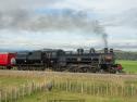 Date: 02/05/19 16:52 Re: Slanted Cylinders? Author: DWDebs/2472 Slanted cylinders are located higher above the rail than with level cylinders. I suspect that slanted cylinders were necessary to clear high-level boarding platforms. Later designs - NZR class K 4-8-4 [built 1932-1936], and NZR class J/Ja 4-8-2 [built 1946-1956] - also had inclined cylinders.
General info on NZR class Ab Pacifics: https://en.wikipedia.org/wiki/NZR_AB_class - Doug Debs P.S.: The locomotive in the photos, NZR class Ab 608 Passchendaele, commemorates New Zealand's sacrifices in WW1. "Ever since 1917, Passchendaele has been a byword for the horror of the Great War. In terms of lives lost in a single day, the failed attack on Bellevue Spur on 12 October was probably the greatest disaster in New Zealand’s history." Date: 02/05/19 17:18 Two more examples? Author: Railpax71 I went looking in my New Zealand file and found these two. Previous post mentioned platform clearance and in the second picture you can see this.
Any additional info on these pictures appreciated.   Date: 02/05/19 17:53 Re: Two more examples? Author: gbmott This was also very common practice in the UK (below) up to the very last steam locomotives built there but I have no idea why and would be curious to know.
Gordon 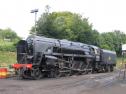 Date: 02/05/19 18:33 Re: Two more examples? Author: wcamp1472 It has to do with reducing the disparity of the unequal arcs traversed during the power strokes of horizontal cylinder mounting, where the horizontal center-line of the cylinders coincides with the centerlines of the drivers’ axles.
This is best exhibited by the geometry of cylinders on the same centerlines as the axles. If you stop the loco with one of the drive pistons exactly at the halfway point of the stroke, i.e: the 17” mark of a 34” stroke loco, At this point, the crank on the main driver will NOT be at the circle’s 180-deg position ( Zero degrees is assumed to be at the TOP of the driver, 90-deg would the FDC, Front Dead-center, 180-deg would be the exact mid point of the stroke, 270-deg would be the BDC, Back Dead-Center). Since the main rod swings in an arc, whose center is the wrist pin (crosshead pin), when stopped with the piston at the exact midway of it’s travel ( 17”), it cannot be that the driver’s crank will also be at the 180-deg mark of the crank circle. In America, remember that the center-line of the cylinders is at the same centerline as the drivers. An example is that ( for purposes of this explanation) the mid-point of the piston’s travel leaves the crankpin 5-degrees shy of the 180-deg mark at the driver’s rim. The same angular difference is true at the top of the crank circle: at ZERO degrees. However, with the piston, again at the midpoint of the stroke, has the crank 5-degrees ahead if the ‘zero’ mark at the very top of the driver, on it’s vertical center-line.. So now, the crank travels 190-degrees up the back of the crank circle, and only covers 170-degrees over the front half of the circle. ( this presents a true conundrum for ‘valve gear setters’ [ those skilled machinists and valve gear designers]). That disparity also exhibits the challenge of different cylinder volumes, front and rear of the pistons There is more steam admitted over the back 190-degrees, than is admitted over the front 170-degrees. However, this disparity of admission periods can be partially off-set by raising the cylinders, at an angle, up above the centerline of the driver axles. Typically, you can get maybe 3 or 4 degrees of more-favorable ( better equalized) valve events and more-even ( thrusts) power strokes , over the entire 360-degrees of the power stroke circle. That objective is more easily accomplished in the ‘toy-sized’ engines used around the world. In the US of A, we tended to design locos to be real bulls at handling heavy trains, steep grades, and twisting curves. European railroads focused on perfecting their roadbeds to be virtually flat, and straight-lined. So, their engines lent themselves to the complexities like multiple-cylinders, in a single rigid frame, and exotic, crank-axles, as well as the tilted cylinder designs. Not so much, in America... W ( see also, subjects related to “Angularuty of the Main Rod”, on locomotives... Also, a mitigating factor of the disparate volumes, is the fact the piston rod, out the rear of the piston, displaces some cylinder volume—— so that, in actuality, the apparently disparate cylinder volumes, caused by the “angularity problem”, [volumes ahead of the piston vs. the equal volumes displaced by the piston rod, thru the rear cylinder head]. In American practice, the “volume disparity” is NOT as great as it might appear to be .) Edited 2 time(s). Last edit at 02/05/19 19:18 by wcamp1472. Date: 02/05/19 18:46 Re: Two more examples? Author: BoilingMan You're The Man, Wes!
SR Date: 02/05/19 19:18 Re: Two more examples? Author: Railpax71 Old school engineering with a basis in geometry. Lost with Lucas the Prince of Darkness.
Date: 02/05/19 19:30 Re: Two more examples? Author: wcamp1472 LOVED the Lucas reference...
I used to have Lucas accessories on my bicyles years ago..and yes , I get it about their design mysteries ... get home before dark.. Wes. Date: 02/05/19 20:09 Re: Two more examples? Author: Check_A1E_Perf I'm still having trouble accounting for the +/- 5 deg on the main rod but I sure do feel a whole lot smarter after reading Wes's post. Brilliant stuff! Thanks Wes.
Posted from Android Date: 02/05/19 20:42 Re: Two more examples? Author: wcamp1472 It’s simply a matter that as the big-end of the main rod moves down, it follows a circular arc who’s center is the wrist pin.
if it’s an 8-foot main rod, that circle described would be 16 feet. If you dropped the big end of the main rod to the ground, it’s crank-pin hole would fall well ahead of the crank pin, & rail’s tangent point, at the bottom of the tire. Another way to look at it is picturing the big-end of the main rod were swung vertically , up & down,, it would rotate about the wrist-pin in a circular arc.—— main rod at horizontal ( with the piston at midway point), it would line up with the center of the axle, if lowered , it’s center could no longer intersect the vertical centerline through the axle’s center, it is conforming to an 8-foot arc... To connect the big end of the min rod to the crank pin, you would have to turn the driver until the crank pin lined up with the hole in the mainrod. Or, ( if the crank was at the very top, or very bottom of its circle) you would have to move the piston from ii’s center-of-travel point a couple of inches ( rearward) to get the main rod hole over the crank pin. The 5-degree numbers are illustrative only,, & are used for examples... Wes not proofed, yet... Date: 02/05/19 23:19 Re: Two more examples? Author: JimBaker Looking up BR 92212, Specs given are that was a Two-cylinder loco, the last class to be built by British Rail.
This loco is based at Mid-Hants Railway in Hertfordshire. Ref: Wikipedia ... James R.(Jim) Baker Whittier, CA Date: 02/06/19 03:05 Re: Two more examples? Author: utwazoo wcamp1472 Wrote:
------------------------------------------------------- > LOVED the Lucas reference... > I used to have Lucas accessories on my bicyles > years ago..and yes , I get it about their design > mysteries ... > get home before dark.. > > Wes. And maybe no cold beer in the fridge (old English joke) Date: 02/06/19 04:09 Re: Two more examples? Author: LoggerHogger Slanted cylinders come on locomotives of all sizes.
Martin 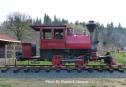 Date: 02/06/19 04:29 Re: Two more examples? Author: wcamp1472 NOW, That’s ridiculous...
The drivers are so small & it’s a ‘soaker’... looks like it would struggle with just a caboose !! So, what’s the real benefit of slanted cylinders ? But, still a cute loco.. W. Posted from iPhone Date: 02/06/19 06:11 Re: Two more examples? Author: elueck Lots of Porters and Glovers (tiny locomotives by any standards) were built that way, but the why is lost with their designers.
Date: 02/06/19 13:20 Re: angularity Author: timz > this disparity of admission periods can be
> partially off-set by raising the cylinders, > at an angle, up above the > centerline of the driver axles If the stroke is unchanged, and the main rod length is unchanged, the disparity will be unchanged. Raise the cylinders 90 degrees to vertical -- it will be the same disparity, just top/bottom instead of front/back. Date: 02/06/19 14:25 Re: angularity Author: Check_A1E_Perf Yep, that did it! Makes total sense. Thanks Wes!
In another thought, I had previously thought this incline was to help drain condensation toward one end of the cylinder but that would necessitate some type of passage past the piston to allow drainage... Posted from iPhone Edited 1 time(s). Last edit at 02/06/19 14:28 by Check_A1E_Perf. Date: 02/06/19 14:56 Re: angularity Author: LarryDoyle What makes anyone think they should be horizontal?
-John |