| Home | Open Account | Help | 293 users online |
|
Member Login
Discussion
Media SharingHostingLibrarySite Info |
Steam & Excursion > Maximum output of coal and oil fired boilers.Date: 02/08/19 14:51 Maximum output of coal and oil fired boilers. Author: Klondyke I am looking for help about the limits of oil fired boilers, and I think some of you guys will know the answers.
I have a lot of test data for coal fired boilers in the US, France and the UK. The picture on their limiting output is quite simple. With good quality coal (13500+BthU/lb), you can with a good draughting system get 1000lbs steam/sqft grate/hr, if you fire enough coal. On e.g. a Niagara, add in roundly 10% of recycle from the feedwater heater and you can provide 110000lbs/hr to the cylinders, just about enough to give you 6600IHP at 58% cut off and 75mph. in France Chapelon pushed boilers to 1300lbs/sqft/hr to support his claims. This is wonderful publicity, but irrelevant to normal operation, not least because unburned coal losses begin to rise steeply above about 600lbs/sqft/hr, so steaming at these high rates is very uneconomic. Kiefer says that for this and other reasons the NYC had learned that it didn’t pay to steam boilers hard, and in the Niagara test report, he notes that a cylinder rate of 63000lbs/hr,(just over 4000IHP) say 550lbs/sqft grate /hr would be ‘above average passenger working’. I don’t know of any steam services that were scheduled to work at much over 650lbs/sqft/hr. In normal service in the UK you might, once in a lifetime, get 900lbs/sqft/hr for a few minutes if the crew were trying really hard. The only data I have on oil burners is from ATSF tests on their 4-6-4s and 4-8-4s in Farrington’s book. These have 99 and 108 sqft grates respectively. The maximum power quoted for the 4-6-4 is about 4300IHP, which requires about 550lbs/sqft grate/hr. In this case, the power the engine can deliver is likely limiting; even at 70mph this would require 40% cut off. From the few logs I have seen, they didn’t run at much over 3000IHP, or 400lbs/sqft/hr. The 4-8-4’s maximum power is given as about 5500, which translates into about 68000lbs/hr evaporation or 630lbs/sqft/hr. This design has much larger cylinders, and can deliver this in about 30% cut off at 80mph. The engine could deliver as much power as a Niagara in but 40% cut off at speed if it were possible to steam the boiler at the same level. On steep mountain grades at 30-40 mph, the maximum is 4700- 5100IHP, a similar evaporation to above, at 50 and 40% cut off respectively. In service, there are some logs in Farrington’s book that shows 2900s delivering 4000-4500IHP for significant stretches (less than 500lbs/sqft/hr), but these were gaining massive amounts of time, so I’m thinking the norm was less than this. In line with this, on the 3765 tests, it did not seem to exceed 4000IHP on the long climb from Topock to Wampai. An extra 1000HP should have been possible and would have made a big difference to the running time. Overall, I’m left with the impression that you can’t push oil fired boilers as hard as coal fired ones at equal grate size, despite the higher calorific value of the fuel. Is it that the ATSF were saying ‘we’ve no intention of steaming them at more than 650lbs/sqft/hr, so no point testing above that’? Or is it that there was some inherent limitation of oil burners that limited maximum output/ sq ft grate? For what it’s worth the ATSF data seem to say that, like coal, unburned losses rise steeply when you steam much above 600lbs/sqft/hr. Thanks for any insights you may be able to offer. Date: 02/08/19 15:15 Re: Maximum output of coal and oil fired boilers. Author: DWDebs/2472 A good source of information on oil firing vs. coal firing vs. boiler evaporative capacity is the book "The Steam Locomotive in America: Its Development in the Twentieth Century" by Alfred W. Bruce, published 1952 by Bonanza Books. Used copies are available on www.abebooks.com and amazon.com. IIRC, Bruce was the chief designer at American Locomotive Company.
I believe that the author states that [for typical USA coal], a coal-fired boiler needs about 1.3 times more grate area than an equivalent oil-fired boiler. So an oil-fired heavy 4-6-2 (S.P. 2472, for example) with 70 square foot grate area [firepan area, technically] is roughly equivalent (in boiler evaporation capacity) to a coal-fired boiler with 91 square feet of grate area. 91 square feet of grate requires a 4-wheel trailing truck to support it, so an oil-fired heavy Pacific 4-6-2 is roughly equivalent to a coal-fired 4-6-4. - Doug Debs Date: 02/08/19 15:38 Re: Maximum output of coal and oil fired boilers. Author: Goalieman Klondyke Wrote:
------------------------------------------------------- > I am looking for help about the limits of oil > fired boilers, and I think some of you guys will > know the answers. > > I have a lot of test data for coal fired boilers > in the US, France and the UK. The picture on their > limiting output is quite simple. With good quality > coal (13500+BthU/lb), you can with a good > draughting system get 1000lbs steam/sqft grate/hr, > if you fire enough coal. On e.g. a Niagara, add in > roundly 10% of recycle from the feedwater heater > and you can provide 110000lbs/hr to the cylinders, > just about enough to give you 6600IHP at 58% cut > off and 75mph. in France Chapelon pushed boilers > to 1300lbs/sqft/hr to support his claims. This is > wonderful publicity, but irrelevant to normal > operation, not least because unburned coal losses > begin to rise steeply above about 600lbs/sqft/hr, > so steaming at these high rates is very > uneconomic. Kiefer says that for this and other > reasons the NYC had learned that it didn’t pay > to steam boilers hard, and in the Niagara test > report, he notes that a cylinder rate of > 63000lbs/hr,(just over 4000IHP) say 550lbs/sqft > grate /hr would be ‘above average passenger > working’. I don’t know of any steam services > that were scheduled to work at much over > 650lbs/sqft/hr. In normal service in the UK you > might, once in a lifetime, get 900lbs/sqft/hr for > a few minutes if the crew were trying really > hard. > > The only data I have on oil burners is from ATSF > tests on their 4-6-4s and 4-8-4s in Farrington’s > book. These have 99 and 108 sqft grates > respectively. The maximum power quoted for the > 4-6-4 is about 4300IHP, which requires about > 550lbs/sqft grate/hr. In this case, the power the > engine can deliver is likely limiting; even at > 70mph this would require 40% cut off. From the few > logs I have seen, they didn’t run at much over > 3000IHP, or 400lbs/sqft/hr. > > The 4-8-4’s maximum power is given as about > 5500, which translates into about 68000lbs/hr > evaporation or 630lbs/sqft/hr. This design has > much larger cylinders, and can deliver this in > about 30% cut off at 80mph. The engine could > deliver as much power as a Niagara in but 40% cut > off at speed if it were possible to steam the > boiler at the same level. On steep mountain grades > at 30-40 mph, the maximum is 4700- 5100IHP, a > similar evaporation to above, at 50 and 40% cut > off respectively. In service, there are some logs > in Farrington’s book that shows 2900s delivering > 4000-4500IHP for significant stretches (less than > 500lbs/sqft/hr), but these were gaining massive > amounts of time, so I’m thinking the norm was > less than this. In line with this, on the 3765 > tests, it did not seem to exceed 4000IHP on the > long climb from Topock to Wampai. An extra 1000HP > should have been possible and would have made a > big difference to the running time. > > Overall, I’m left with the impression that you > can’t push oil fired boilers as hard as coal > fired ones at equal grate size, despite the higher > calorific value of the fuel. Is it that the ATSF > were saying ‘we’ve no intention of steaming > them at more than 650lbs/sqft/hr, so no point > testing above that’? > > Or is it that there was some inherent limitation > of oil burners that limited maximum output/ sq ft > grate? > > For what it’s worth the ATSF data seem to say > that, like coal, unburned losses rise steeply when > you steam much above 600lbs/sqft/hr. > > Thanks for any insights you may be able to offer. > Mr. Wes Camp. Your doorbell is ringing!! Posted from iPhone Date: 02/08/19 16:57 Re: Maximum output of coal and oil fired boilers. Author: wcamp1472 I have some thoughts, but no answers.
i have never worked on, or fired an oil fueled locomotive. I would be interested in HotWater’s comments, he has relevant experience on both types. So here is my experience, ideas and questions. Indicated Horse Power. Derives it’s name from a cylinder ‘ indicator’ apparatus, common in stationary engines, powering factories and early, physically huge reciprocating, low speed engine ps used in power plants like the early days of NYC subways. The indicator used a card mounted on a rotating drum, the drum was connected to the crosshead, and restored to its original position by an (interior). coil spring. A pen, or pencil-lead was connected to a small cylinder fed by a copper line from one end of a cylinder. When operating, the indicator was designed to take one stroke of the piston and disengage. The testers would bring the flywheel up to a steady speed, with a steady load ( electrical) the drum would oscillate drawn by the string connected to the crosshead ... A cam on the drum would lift the pen after one drum rotation. The test engineers would manually release the trigger holding the pen clear of the card. The pencil would ruse and fall according to the pressure in the cylinder —- often moving very quickly, up and down. The test engineers would release the pen and the drum would rotate, ant the end of one rotation, the pen was lifted and latched free if the spinning drum. The trace recorded roughly resembles the profile of a high-topped sports sneaker. The sole of the sneaker represents the ( atmospheric pressure) return of the piston with the exhaust port opened for 80% of the return travel, the heel and the back of the sneaker represents the pressure increase in the cylinder with the inlet port opened. The ‘ankle hole’ , top of the sneaker, represents the inlet port admitting full steam chest pressure into the cylinder with the moving piston. The portion of the sneaker with the laces-holes represents the decreasing cylinder pressures once the inlet valve closes, allowing for the resudual heat of the steam to exert pressure on the piston. The top of the toe around to the front of the sole represents the opening of the exhaust rings, to allow the steam to escape... All of that trace is captured on the “indicator cards” : one stroke, of one side of one piston, with the vertical portion powered by the steam trapped in the cylinder, until exhausted... For stationary and marine engines, RPMs are relatively low and slow. The power is calculated from the size (area) of the “sneaker shaped” trace. At short valve cut-offs, the flat part at the top of the curve ( valve chest pressure) of the pressure curve would represent the open time of the admission port. Thus, the expansion curve would wotkd be a longer portion of the piston travel —- a lightly loaded engine, with not much of a a power demand. For more power, the admission valve stays open for a longer flat-trace, at the top of the trace card. In loco practice one can conceive of the admission port opened for 80-percent of the stroke. Thus producing thre grearest power. The sneaker-shape varies as power is adjusted. At factory-engine RPMs, typically under 100 rpms, getting a readable trace, that looks roughly like a sneaker’s -profile is fairly easily obtained. Locomotives run at speed approaching 300 RPMs , or, 5 revolutions a second. Try capturing a ‘readable’ trace’ in 1/20th of a second, with pen and paper. HA! Back in the lab, the trace is copied using a planiimeter: a measuring device that calculates the total area contained in the described trace. Then using pressure/volume equations, the numbers are combined with the Tachometer readings of the flywheel. Now you have the unit of work, multipled by time— yielding ‘“indicated HP”. ( the word processor is getting over stressed... to be continued) W not proofed, yet..pardon any obvious typos... Edited 1 time(s). Last edit at 02/08/19 19:36 by wcamp1472. Date: 02/08/19 17:57 Re: Maximum output of coal and oil fired boilers. II Author: wcamp1472 My skepticism comes from the disparity of engine speeds between stationary, factory engines — in speeds about 100 RPMs, and loco speeds ( at high HP) in speeds of 300 RPMs. The inducator cards using Rube Goldberg ( string and spring) technology obtained from indicator cards of high speed locos, 300 RPMs is 5 revolutions per second, or 20 milliseconds, 10 milliseconds for one half of a revolution, or one stroke of a two-stroke, one complete revolution.
The traces at high RPMs are virtually a squiggly line, not a true record of an accurate Pressure/Volume curve. Back at the lab, the cards are laid flat, and the sneaker-shoe outline is traced using a planimeter —- a mechanically operated analog calculating device whose output result is the area enclosed by the closed-loop trace. At low Locomotive speeds the trace yields a better, more reliable result than one obtained by the “string-and-spring” device. The traces at high speed/high HP readings are hardly more than squiggly lines...there’s no way a scientifically rigorous result can be obtained with such primitive devices. Thus, I am highly suspicious of HP readings precede by the term “Indicated HP”. To me, it’s total bull-pucky ... I have dreamed of a laser-accurate, linear-travel measuring device, coupled with an instantaneous steam pressure transducer signals, displayed on an X-Y, modern oscilloscope ...coupled to planimeter software, yielding scientifically-accurate results and numbers. Such readings could be continuous, capturing the 4-stokes of one driver revolution, at the highest possible driver rotation speeds. So, avoid speculations based on “spring-and-string” indicator cards, when trying to compare capabilities with two types of fuel. Secondly, you cannot compare ‘grate areas’ between grate-equipped coal burners and single-point oil burners used in modern locos. Don’t discuss grate areas of oil burners.... it is a true oxymoron. Also, once common ‘Bunker C’, resid-oils, had much higher heat-value, per pound than lighter fuels, used today. Bunker C was virtually “liquid Carbon’....much hotter and much longer flame length, than the lighter fuels currently used. Oil burners are very much dependent upon the mass of bricks in the fire-pan ( compared to the simple brick-arch in modern coal burners. The firebed of a coal burner can be a much larger source of radiant heat in the firebox combined with the immense amount of fines that burn entirely ( suspended) in the high velocity air stream through the firebox..never touching the grates. We are lleft with the two styles of fireboxes, having been derived, over time, from trial and error engineering, and not much else.. The improvements were gradual, evolutionary, and largely the result of shared experiences amongst the loco designers in the rail industry and in the loco-manufacturing industry.... You posed very thoughtful ideas and challenging problems. But, the “indicated HP” figures are totally a salesman’s concoction —- and really not very valuable as a comparison tool —- because the instrumentation was so inadequate to high speed valve events. Using industrial, electronic measuring, we could easily derive more rigorous testing results to build credible loco comparisons. Another concept I had was using, permanent, strain-gauge equipped tender drawbars, and accurate speedometers...to derive real-time HP readings, while boiling down the main at 80-per.😆🏁 🏁W🏁 Edited 1 time(s). Last edit at 02/09/19 06:09 by wcamp1472. Date: 02/08/19 18:04 The "Sneaker" Author: LarryDoyle Good choice of words, Wes. I love it.
Here's a sketch of the Indicator. The large drum holds a paper, and is rotated by the cords and spools to the left which are clipped to the valve gear to provide motion. The cylinder to the right contains a piston which responds to cylinder pressure, with a mechanism to move the pencil in response to pressure changes. Thus the pencil line drawn on the paper on the drum will show the pressure in the cylinder, on one side of the piston, as it rises and falls during one relovution the the drivers. The second diagram is a sample diagram from a locomotive running at 29 mph. The letters indicate: V. Base line. Perfect vacuum. A. Atmospheric line. 14.7 psi above V B. Point of admissionat beginning of stroke. B to D. Admission Line. Show the "Lead" of the valve setting. D to E. Steam Line. E is the point of cutoff E to F. The expansion curve. F is the point of release - where the "Chuff" comes from. F to C. Line of back pressure C to B. C is the point of compression, and C to B is the compression curve. If you're further interested in this sort of thing download the Dockstaeder valve gear diagrams, which dynamically show these charts at various valve settings for various valve gear types. Sometimes you can find photographs of locomotives with a small cab or shelter temporarily built above or in front of the cylinder of an engine, to house this test equipment and shelter the operator. -Larry Doyle 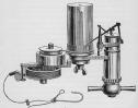 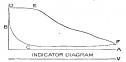 Date: 02/09/19 05:56 Re: The "Sneaker" Author: SR2 Thank you, Wes, for bringing up "Bunker C". My first job was as a "student assistant" to the Chief Custodian
of our local high school. It was the mid-60s and natural gas was just getting to the upper midwest. We had two boilers in the school. One was a bin-feed stoker coal-fired boiler a very nice set up on a huge boiler, the other a hand-fired coal boiler of the same size. The hand-fire was converted to gas/fuel oil boiler. When the temperatures got to about zero, the gas company would call and we had to go to oil fuel. The point of this whole thing, we used Bunker C which we heated until it could be atomized by the burner. The boiler produced steam better on oil than on natural gas. I was told it was due to the high btu per gallon of the Bunker C. That proved out when the burner was altered to use #2 Fuel Oil due to issues with the heavy fuel oil "gelling" in the outdoor tank when the temperatures were low. On conversion, we used a great deal more fuel (in gallons) to produce the same amount of steam. My point: Bunker C and normal fuel oil are two distinctly different products with a great deal different BTU/gallon rating. Date: 02/09/19 06:03 Re: The "Sneaker" Author: wcamp1472 YES!
I call it “Liquid Carbon”.. It makes all the difference in the World.. W. Date: 02/09/19 07:01 Re: The "Sneaker" Author: BAB Larry Doyle, it must have been quite a ride for the operator of the device. There were many tools developed for steam engine operation that were very uniquie have seem some here and there on display. Just wonder if Martin has any in his collection that he might show. Boyd in Cold windy snowie Chiloquin OR where winter has come back in force.
Date: 02/09/19 11:15 Re: The "Sneaker" Author: nycman Textbook "Basic Steam Locomotive Maintenance" by D. C. Buell, pages 171-175 has a detailed description of the Indicator Diagrams, written back when they were in use. Technology of the day, a pencil, drew the diagram. Al Stauffer's "Thoroughbreds" pages 54-61 shows one of the testers "shelters" built on to the pilot of the first NY Central Hudson 5200 and a description of the testing it went through.
Date: 02/09/19 11:54 Re: The "Sneaker" Author: LarryDoyle BAB Wrote:
------------------------------------------------------- > Larry Doyle, it must have been quite a ride for > the operator of the device. There were many tools > developed for steam engine operation that were > very uniquie have seem some here and there on > display. The indicator was actually invented by James Watt for analyzing his coal mine water pumps! Date: 02/09/19 13:25 Re: Maximum output of coal and oil fired boilers. Author: sgriggs Klondyke,
I think I understand what you’re after—data on boiler evaporation vs oil firing rates. Are you trying to see where the analog to the “grate limit” is on oil-fired locomotives? I would start as you did with the Farrington book on The Santa Fe’s Big Three, but as you found, there is not a lot of data on the locomotives being fired to their limits. I went searching the references I have. There is some road test data on oil-fired UP locomotives in one of the Kratville books I have. I can’t remember off the top of my head if it is 4-8-4 or 4-6-6-4 data, but it gives the amount of oil used and water evaporated to pull a train of specified tonnage over the test route for various trips. The amount of running and standing time is also given. As you might expect, the locomotives were not being pushed to their evaporation limits—these were tests to measure economy in real-world scenarios where the railroad was trying not to waste fuel. If you’re interested, I can send via PM or maybe post as a photo here. i also consulted a new book in my library titled, “The American Steam Locomotive in the Twentieth Century”, written by Tom Morrison (published 2018 by McFarland). This book has a lot of interesting information in it, and is may be most useful as a survey of contemporary information sources in the steam era—it is very well footnoted. While searching for references to oil fuel, I came across mention of testing the Southern Pacific Railroad conducted in the late 1940s. I will quote an excerpt: ”In 1947, faced by rising fuel costs, the Southern Pacific built a standing test plant at its Sacramento shops, obtaining permission from Walter F. Collins, Engineer of Tests on the New York Central, to use his patented method of spraying measured amounts of water into the cylinders to cool the steam, thereby simulating the energy used in the cylinders, extracting the same mass of water as steam from the exhaust passage ways. The water nozzles could reduce the steam temperature to any desired level, down to saturation. Gate valves controlled the steam pressure in the cylinders. By this means a complete range of firing and evaporation rates could be tested and boiler efficiencies evaluated and compared. At the same time, the Southern Pacific commissioned experiments on a quarter-scale model of a complete firebox, boiler, and front end at the Battele Memorial Institute and ran dynamometer tests with thirteen combinations of nozzle diameter, splitter type and dimensions, and distance from nozzle to base of stack.” The testing done at Sacramento was the same type of boiler testing the NYC did at its Selkirk shops using the same method patented by W. F. Collins, except it was done on oil-fired locomotives. This opens the possibility of a source of high quality engineering test data, but performed on oil-fired locomotives in a stationary test plant. I did some Google searches, and found the following two articles, from the time of the testing: 1947 Railway Age article 1948 Modern Railroads article The articles describe the test plant and methodology in a bit more detail, but do not provide any test data. Perhaps a source like the Southern Pacific Historical Society or Battele Memorial Institute archives could find a test report? There is probably an SP railroad forum somewhere that could be asked if any SP subject matter experts have ever seen test reports from the Sacramento shops boiler tests. Lastly, I think I have an article from the Engineer on Southern Pacific cab forward locomotives written in the 1920s or 30s that may have a little information on firing and evaporation rates. I’ll see what I can find. Scott Griggs Louisville, KY Edited 1 time(s). Last edit at 02/09/19 13:44 by sgriggs. Date: 02/09/19 14:18 Re: Maximum output of coal and oil fired boilers. Author: LarryDoyle I couldn't find a photo of a pilot mounted shelter for housing the indicator apparatus and it operator, but here is a suggestion for building one. They just looked like a black painted wooden box. Or, coffin. Or outhouse.
-LD Edited 1 time(s). Last edit at 02/09/19 14:20 by LarryDoyle. 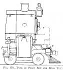 Date: 02/10/19 14:27 Re: Maximum output of coal and oil fired boilers. Author: Klondyke Thanks very much to all for the comments so far.
There are two separate and very interesting discussions going on, one about indicators and the other about oil firing! I should start by saying that I do agree that indicator diagrams back then should be treated with considerable scepticism for all sorts of reasons, but will come back to explain why I think the values I quoted for the Niagara and ATSF types, whilst maybe not pinpoint accurate are as good measure of the cylinder power being developed as you need on the tests I quote. However, I don’t think the indicator question really impinges on the point I’m making. All I’m saying is that the maximum evaporation rate of the ATSF types seems to be less than those from coal boilers of a similar grate size. It seemed that unlike coal fired boilers which can be steamed way above their normal ‘sensible’ economic limits if so desired, oil boilers could not. I am grateful however to Doug Debs for the reference he quotes. I haven’t seen this and will certainly look it up. The idea that an oil grate can generate 30% more steam than an equal sized coal grate is quite the opposite of what I was thinking. Time for some more reading. As with all these questions, getting some good data is essential to sort things out, as Sgriggs suggests , and if the SP data he mentioned can be located this could provide the answers. Because yes, what I’m really looking for is whatever it is that limits the output of oil fired grates, The Bruce reference suggests that the ATSF 4-8-4 had a grate equivalent to about 140 sqft, which should easily be able to deliver 110000lb/hr to the cylinders and 6500hp- way more than the ATSF said. There is no way that 3766’s ca 26mph climb to Cajon unassisted with 852 tons can be surpassed- this was at near maximum NTE in maximum cut off, flat out, but its climb to Wampai seems well below this standard, though this is maybe because the train was on time. On indicators, I should say that I am no expert on their design and operation with the kind of knowledge shown in the comments of WCamp 1472 and Larry Doyle. I am however familiar with the general problems they describe. I was looking at some actual indicator cards from the 1930s recently and thought ‘they were using these?!’ Developments towards electronic measurements were being made in the 1930s in both the US and France, and there are electronic cards from South Africa in the 1980s. A one off old style indicator card is doubtless of dubious value. However, I have looked at hundreds of results taken from tests where a wide range of additional measures were taken. Depending on the test protocol, there are several different ways in which these measures can be used to do sanity checks on the indicator results. Further, it is now possible to calculate theoretical indicator diagrams and see how the results compare with reported measures. From this work, I can quote examples where a brand new indicator design in the 1950s, allegedly accurate to +/- 2% gave results up to 20% out during their first three years of use, until the problem was identified and fixed. (They were however better for road testing than the old Maihak style indicators, which needed a shelter of the kind Larry Doyle mentions above the buffer beam. A fun ride for the operator, flying along at high speed behind a few planks of wood. I have plenty of pictures if only I knew how to post them). The new ones could be read in the dynamometer car. In another case, one company’s indicators always seemed to read up to 10% high, which bolstered their (incorrect) belief that they were better than everyone else. And, it seems clear by comparing modern and steam age diagrams that the equipment back then was quite unable to measure rapid pressure changes especially around TDC, so odd looking diagrams appeared. In some cases (including some ATSF diagrams) you look at the rapid pressure fluctuation during admission and think, ‘I don’t believe that’. There are some crazy indicator diagrams shown by Chapelon when they got the set up wrong. What he concluded when he got the set up better was that the crazy diagrams nonetheless had the right areas and hence gave the right MEPs! So maybe Lady luck was smiling on these brave pioneers. I have looked at hundreds of data points from Altoona, on the K4, K4F, L1, I1S, I1E, T1 and Q2 tests. The conclusion from this exercise is that, miracle of miracles, the indicator results from as far back as 1912 were, with a few odd exceptions as good as you can hope for, and by the 1940s they were very competent. There is likewise enough additional data on the NYC and ATSF tests mentioned to sanity check their indicator results, and they can’t be far wrong. So I think we have a very good sense of how much power the engines of these locos were delivering at various cut offs and speed, and the worries about indicator diagrams, whilst real, do not apply in these cases. I think it will be agreed that a proper appreciation of how much power an engine can develop at speed, as shown by indicator diagrams, given sufficient steam, is essential to understand what locomotive classes can and cannot do. I think we can now do a decent job in estimating this for any class of interest, maybe 100 years too late, but interesting nonetheless. Having said which, there are some features of American designs that make this a bit more difficult. |