| Home | Open Account | Help | 240 users online |
|
Member Login
Discussion
Media SharingHostingLibrarySite Info |
Steam & Excursion > What is true about counterbalance weight in driver wheels? EBTDate: 11/14/20 04:55 What is true about counterbalance weight in driver wheels? EBT Author: PlyWoody Very early into the hobby of steam locomotives I (like 13) was told that some counterweights in driver wheels of steam locomotive may have had inserts holes filled with lead. Is that known to be true? 2nd question. At some point in the lives of some locomotives that lead can’t take the pounding and turns into lead oxides, a power with no weight of value so the drivers are not balanced and driver pounds the rail.
3rd question: If they cast new steel driver wheels for East Broad Top #14, will the steel be of the same weight as the present iron driver wheel, and not need new design counterbalance section on those drivers. With the low speed of the EBT ng engine, is there any question about being out of balance? Steel can have different weight per cubic measurement based on its mixture, but iron is one weight. Were there any lead weights put in the counterbalance section of driver wheels of any narrow gauge locomotives? Date: 11/14/20 05:59 Re: What is true about counterbalance weight in driver wheels? EB Author: BAB So what you are saying in one place is the lead not being a solid mass some how without any loss from the container looses weight? How is that trick done?
Date: 11/14/20 07:01 Re: What is true about counterbalance weight in driver wheels? EB Author: wcamp1472 The driver centers are cast with hollow voids--- to have molten lead added.
Its variable volume allows fine tuning of the amount of counterbalance desired. The weight voids are covered with suitable steel plates, securely welded over the voids. Yes, over time the lead gets pounded to dust.. it's trapped, so the weight doesn't 'go' anywhere. The mass of the installed weight remains constant, yet the centrifugal force increases with RPMs--- soon the wheels could be lifted off the rails. ( see: the Scottish games of men throwing whirled weights) Lerger diameter dirvers require less lead than smaller drivers when operated at passenger train speeds. 70" drivers require more mass than than 80" drivers, to provide the same counter-mass cushioning effect ( most desirable at the pistons' dead-centers).. However, the whirling mass affects the wheels throughout the 360-degrees of rotation. When drive designers in the early 1900s thought that they could balance 100% of the weight of the piston, piston-rods, main rods, they used too much lead in the voids.. At high speeds, the whirling over-weight counters lifted the whole wheel off the rail when rounding over the top of the arc, and pounded kinks into the rail, when at the bottom of the arc. Thus, with hollow counterweight voids, they could adjust, by experiment, the amount of weight to avoid track damage. At the end steam development, they went for lighter weight pistons and hollow piston rods. lightter crossheads, etc. The lighter the reciprocating masses, the less counterweight would be needed. Its a myth the roller bearing rod application 'were light weight'. Complete Roller bearings applications weighed more than simple bronze bushings, commonly used . Many RRs had large fleets of locos without rollers, so they still needed to retain a mechanical force to lube the plain rods, anyway. There was no labor/cost saving advantage to recoup the added cost of roller bearing rods. Rollers on the axles were almost imperative, not so much for the rods. Replacing the worn plain bushings was simply a matter of pulling the caps & nuts, yank out the old bronzes, and insert new bushings. ( yanking was aided by tapped holes in the outer edge of the bronze (segmented?) inserts....a plain bolt was screwed into the holes, and the worn bushing pulled out...new bushings were simply slid in place. The whole operation took less than 5 minutes per axle. Designers used lighter rods and configurations .... see UP's use of plain bearings, as well as SP, and many other 'roads that eschewed roller bearing rods expenses. The best example is the mods to the tandem-drive rods of Timken's design, to N&W J #611. Their efforts replaced the drivers with cast centers using much smaller counterweight voids. Compare pictures the modified wheels on the Js, with the apparent masses of the original counterweight masses. The as-built counterweights are larger than the 611's, reflecting lighter, overall masses. N&W designers eliminated the tandem rods, shortened the crankpins, and used smaller, lighter counter weights on all drivers. Thus, the ability to run a hundred-per. But, engines with 80" 'plain' drivers, spinning at the same RPMs as the Js, would cover more ground per rev, thus the 80" speedsters would be going faster ---at he same Revs as the J --- as it crashes along at it's maximum RPMs for the 70" drivers.. The 80"-equipped locos could still go at much faster axle speeds, easier than the "J" comparison, above; while also going at speeds over the J's max of 110-MPH A Daylight or FEF could always go faster ( easier)! than a J! Designing ideal Counterweighting was always a mysterious process, with no clear, mathematical solutions. The whirling weights ARE always in effect, while moving, and the effective mass increases with speeds. The duplex drives of the 1940s were much better balanced, and most used 2-coupled axles, rather than four, thus saving a lot of mass, and employing much lighter counterweights. See unofficial reports of PRR's T-1s running at over 140 mph.. W. Edited 2 time(s). Last edit at 11/14/20 07:25 by wcamp1472. Date: 11/14/20 07:30 Re: What is true about counterbalance weight in driver wheels? EB Author: BAB W, thanks for all the info as few of us out there know much in depth about this part of steam railroading. I know my remark was kind of snarky but did it anyway possibly causing your reply that I very much enjoyed. Semi truck tires are qute often balanced with some kind of balls that are put inside of there tires when mounting them. I went with old clamp on weights again with my new set but spinning large heavy objects and trying to balance that mass has always been a challange.
Date: 11/14/20 08:58 Re: What is true about counterbalance weight in driver wheels? EB Author: LarryDoyle Here are 3 examples of drivers showing the varying amounts of space different designers allowed for cores in which to pour lead. Like Wes said, some drivers were poured with lead to balance then core holes were welded over. In these examples from 1922 core holes are also in the rim, and sealed by the tire which is shrunk on afterwards.
-LD Edited 1 time(s). Last edit at 11/14/20 09:01 by LarryDoyle. 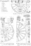 Date: 11/14/20 08:58 Re: What is true about counterbalance weight in driver wheels? EB Author: wcamp1472 The counterbalance-thing is a vey sophisticated concept.
Design Engineers were forever trapped in an unsolvable puzzle. Things varied widely with driver diameter. Another factor is the location of the 'imbalance' with respect to the center of gravity ( mass) of the locomotive structure. Typically, that imaginary point would be near the frame center ( between the drivers) and a couple of feet ahead of the throat sheet of the boiler. If the imbalanced drivers are near there, the whole engine shakes as RPMs increase. That configuration is most common when a 2-wheel pilot truck is used, as on 0-8-0s, 2-8-0s, 2-8-2s & 2-8-4s. As speeds increased as a result of large grate areas allowed by the 4-wheel trailer truck. the shaking became unbearable, especially with light trailing loads. By moving the main crankpin ahead, to the no. 2 axle, and by using a 4-wheel pilot truck, things got much smoother, and the first 4-8-4s came about...and saw many variations and improvements over the years.. But, appreciating the complications is a deep matter. A new concept for me was outlined a month or two ago: Why the PRR went with "Left-Lead" crankpin placement, and the common practice of 90-degree orientation of the two crankpins on two cylindered locos. Seems that the two crankpins pound the rail almost in a sequential 1-2 punch.... and combined with the softer, outer rail support ( weaker roadbed), the right lead locos, across a whole fleet of a couple of thousand locos, pounded the outer rail continuously. Which preresumably meant greater M-O-W expenses and labor time. So, PRR decided to go with the left-lead arrangement, combined with multi-track mainlines ( better support next to adjoining track systems).... in order to go easier on the weaker support of the outer rails, at the edges of the multi track roadbed.... W. Edited 2 time(s). Last edit at 11/14/20 09:08 by wcamp1472. Date: 11/14/20 10:26 Re: What is true about counterbalance weight in driver wheels? EB Author: PlyWoody Big Thanks West for all the background details.
Lead in solid form weights 6.5561 oz per cubic inch Lead oxide (Red Powder) weights 5.3 oz per cubic inch. Where did the 1.35 oz weight go when sealed up in the driver and the solid lead is pounded to dust? My real question was the weight and counterbalances difference of the East Broad Top locomotive #14 receiving replacement steel drivers to replace the iron drivers. Some steel mixtures weight difference from iron. Date: 11/14/20 10:50 Re: What is true about counterbalance weight in driver wheels? EB Author: wcamp1472 At the conceivable track speeds of the EBT, it's not an issue worth losing any sleep over
There's no question that the small amount of carbon added to the iron ( to make it 'steel') is inconsequential. Why would anyone even consider buying cast, gray-iron centers? Steel centers are vastly superior, especially for decades of future use. When originally manufactured ( a hundred years ago?), casting thousands of ( warehoused) driver centers of gray iron was beneficial to the "bottom line" of the loco manufacturers; in today's world....it's not even worth considering. Especially, for one-off applications. IMHO. W. Date: 11/14/20 10:53 Re: What is true about counterbalance weight in driver wheels? EB Author: up833 If lead is exposed to air the very outside layer gets an oxide or carbonate patina, If its incased in a welded shut hole and air proof its not going to oxidize. At any rate you cant pound lead into anyother chemical form (like an oxide) It takes a chemical change not a physical change to oxidize..meaning reacting with oxygen,
RB; Date: 11/14/20 11:28 Re: What is true about counterbalance weight in driver wheels? EB Author: shipsbell What a fascinating topic, I would have never guessed. Thank you W for your information. My question is, in a watch if the balance wheel is heavy on one side it's put into a poising tool to see where the low spot is. The heavy side pulls the balance wheel to the low spot. How does the railroad balance the wheel set. Is it done before mounting or what. Thanks Patrick
Posted from Android Date: 11/14/20 12:14 Re: What is true about counterbalance weight in driver wheels? EB Author: wcamp1472 The purpose of the counterweights is to attempt to counter
the momentum forces at the ends of the piston stroke, where the piston stops and reversed direction ( at the cylinder heads). So, drive-wheel balancing is not the issue, like the balance wheel in a watch. However, from the mid-point of the stroke towards the nearest head, the velocity of the crosshead, piston etc. is slowing down ( with respect to the nearest head) Reciprocating velocities continuously vary at a sinusoidal rate, as the wheels rotate, land cykinder volumes also vary at a sinusoidal rate, from a minimum to a maximum. The piston is connected to the main driver at the main crankpin, and all the other rods are powered from the main crank. ALL Reciprocating engines are faced with this constant problem. For a complex study of counterbalancing, simply look at the crankshaft of today's automotive engines, 6, or eight cylinders. But even they have upper RPM speeds at which they break apart. In the Smithsonian Musem, they used to have a display billet of Chrome-Moly steel, partially machined V-8 crank for use in an Art Arfons' (?) dragster; to replace the conventional cast iron crank. ( so the engine could be revved higher than a cast iron crank.) W (Turbine engines are smaller lighter and more powerful, pound-for-pound, than equivalent power reciprocating machines. I am amazed at the massive amounts of power generated by jet engine a direct descendant of the the original Parsons steam generator.) Edited 1 time(s). Last edit at 11/14/20 12:37 by wcamp1472. Date: 11/14/20 20:09 Re: What is true about counterbalance weight in driver wheels? EB Author: shipsbell W, thank you for taking the time to explain. Patrick
Posted from Android Date: 11/14/20 23:09 Re: What is true about counterbalance weight in driver wheels? EB Author: Elesco For anyone seriously interested in this topic, I recommend obtaining and reading The Steam Locomotive, by Ralph P. Johnson. Both the 1944 and 1945 editions have an entire chapter on the topic of counterbalancing. The book can be viewed free of charge (but not downloaded) at Hathitrust.org.
Mr. Johnson was Chief Engineer of Baldwin Locomotive Works. Date: 11/15/20 18:43 Re: What is true about counterbalance weight in driver wheels? EB Author: Trainhand This thread answers a question I had about the narrow gauge locomotives It has always appeared to me that they have enormous counterweights for their speed and driver size. When ou look at the drivers in a late mountaintype northern, or mikado, they counterweights are noticably smaller.Now another question, did anyone ever geta mike with the main driving rod connected to the 2'nd driver like mountains or northerns? Or did they all come with 2 axle leading trucks?
Date: 11/15/20 19:25 Re: What is true about counterbalance weight in driver wheels? EB Author: wcamp1472 Mikados are, by definintion, all 2-8-2 wheel arreangemnts.
Closest would be the 4-8-2s, Mountains (C&O), Mohawks (NYC), etc When you move the cylinders forward, you must support that weight and the piston forces. You move the cylinders forward to avoid a 'too stubby' mainrod ( only a couple feet long!). Short main rods present many problems with increased power angles, extreme crankpin bushing wear, poor tracking etc. The main reason for developing the 4-8-2 was the severe pounding of the whole engine ( Mikes, etc.) as speeds incresed, driver counterweights were too close to the center-of-mass of the whole engine, Whatever shakes the center of mass, shakes the whole engine... At lower freight train speeds, and earlier times, heavy counterweights were managable; but, as speeds increased (account bigger grate areas & fireboxes), the rough riding and severe track pounding had to be remedied.. Ergo, the arrival of the 4-8-2s & 4-8-4s.. "...counterweights are noticably smaller." That is also due to the higher RPMS at the greater speeds ... remember, that centtifugal force INCREASES the apparent mass, so smaller couterweights have greater effect at greater axle RPMs. ( for fun, look up videos of the Scottish Hammer Throw, note the whirling of the person doing the tossing. the faster the spin, the farther the toss.. That's visible centrifugal force at work) Also, larger diameter drivers have the counterweights farther from the axle centers, so the needed mass is less and less... That's partly why passenger engines had those 80"drivers! W. ( Also, remember that the ‘crank circle’ is about half of the driver diameter... so, the amount of counter weighting needed at the rim would be reduced, from a direct weight-offset proportion [to the reciprocating mass]). (See also: “ cross-counterbalancing”, introduced at the end of steam loco production..) Edited 6 time(s). Last edit at 11/16/20 05:20 by wcamp1472. Date: 11/16/20 08:24 Re: What is true about counterbalance weight in driver wheels? EB Author: Trainhand Thanks for the answers Wes. I hadn'tthought of the weight distribution and the too short main driving rod.
Sam Date: 11/16/20 08:44 Re: What is true about counterbalance weight in driver wheels? EB Author: wcamp1472 It’s almost a straight line ...
From 4-4-0, to 2-6-0, to 2-8-0 to 2-8-2, to 2-8-4, to 4-8-4. The major leap occurred at the bigger grate that needed the 4- wheel trailer —- the 2-8-4. That led to plentyof steam and much higher speeds. Higher speeds battered everything to bits—— so they HAD to move the main driver to axle #2, putting the cylinders further ahead, and requiring a 4 wheel pilot truck... which does a much better job of supporting and guiding the engine— much better than the 2-wheel arrangements. It also took a long time for the factories to build the technology to provide the capacities to manufacture the necessary components.. There were a lot of suppliers to the loco builders... all of which were developing ahead of the shops building the engines.. It took time to develop & to keep up with the demands of increasing freight traffic.. W. Posted from iPhone |