| Home | Open Account | Help | 326 users online |
|
Member Login
Discussion
Media SharingHostingLibrarySite Info |
Nostalgia & History > DM&IR "Straight Air" BrakesDate: 12/19/18 19:56 DM&IR "Straight Air" Brakes Author: LarryDoyle Several posts and photos in the past several weeks have brought up the subject of straight air brakes used on the DM&IR, many captions with the assumption that a high level (above the coupler) air hose on a car or engine indicates that piece of equipment is set up for operation with straight air. I hope this thread can clear up misunderstandings about the DM&IR/CN system as used in Minnesota.
I've been digging thru my meager photo collection for appropriate photos to accompany a thread on this subject, but I don't really have what I was looking for, but Marty Bernard's recent picture of DM&IR engine 310 provides the documentation. Thanks, Marty! See... https://www.trainorders.com/discussion/read.php?11,4691959 Some background information. Minnesota iron ore is heavy. VERY heavy! In the 1890's both of DM&IR's predecessors (the Duluth & Iron Range and the Duluth, Missabe & Northern) determined that the most practical state of the art (i.e. wooden) railroad car that could handle this stuff was 24 ft long between pulling faces, and would carry 30 tons of ore. Ore docks with 24 foot pockets, and ore boats with 24 foot spacing of their hatches locked in this standard. I don't know for sure, but I'd suspect the Eastern unloading facilities also adapted to this 24 foot standard for the ore boats. As steel cars with higher loading capacity were developed, still stuck with the 24 foot standard, designers moved the trucks apart as far as possible eventually winding up with trucks spaced so the wheels were only 11" apart from the next coupled car. Not a convenent space for carmen and brakemen to couple the air hoses, so the standard DM&IR ore cars have their air hose above, rather than below, the coupler as seen in this 1957 photo. Locomotives, even going back to the steam days on their tenders, and even cabooses, were fitted with this high level hose as well. See the picture below of an ore car with the high level hose for operation of the automatic brake. The Duluth and the Two Harbors ore docks are both at the foot of descents of several miles to their lakeside terminals. 2.2% and 3% respectively. Definitely a place where retainers would be used. For those who don't know, a retainer is a gadget with which all freight cars are equipped, which can be manually set at the top of a descending grade to prevent the complete release of the air brakes on that car even if the engineer releases the air brakes on the rest of the train. By manually setting the retainers on, say, the first 20% of the cars in a train at the top of a descending grade, the engineer can then descend with appropriate amount of braking with to control his speed downhill. If it is necessary to reduce braking force while descending - on any train - a complete release of the automatic brakes must be made, then the brakes reapplied. Those headend cars with their retainers set up will not release completely, however. This helps the engineer to keep his train under control on the steep grade. Normally, the cars with retainers set will maintain their set until the train stops at the bottom of the grade and a brakeman manually resets the valve on each car that had been set. DM&IR ore cars are set up with a second brake pipe, also mounted above the coupler, which ties together the portion of the train that will require setting retainers. So each car with an active retainer will exhaust its brake release air into that second pipe, and that pipe is connected to a valve at the engineers control stand to regulate the release of that air. Marty's picture, cited above, shows DM&IR engine 310, equipped with normal MU hoses and an automatic air brake pipe as normal, below the coupler. Above the coupler, the hose with the black handle is a duplicate of the automatic brake pipe connection, and the pipe connecting these two hoses is evident. The hose with the yellow handle is for the straight air system. -John 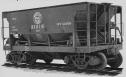 Date: 12/19/18 20:33 Re: DM&IR "Straight Air" Brakes Author: JimBaker LarryDoyle, Are those mechanical linkages on the side of the hopper used to dump the ore or is it for braking?
James R.(Jim) Baker Whittier, CA Date: 12/19/18 21:01 Re: DM&IR "Straight Air" Brakes Author: LarryDoyle JimBaker Wrote:
------------------------------------------------------- > LarryDoyle, Are those mechanical linkages on > the side of the hopper used to dump the ore or is > it for braking? They're for doors. -LD Date: 12/19/18 21:43 Re: DM&IR "Straight Air" Brakes Author: airbrakegeezer LarryDoyle Wrote:
------------------------------------------------------- > > DM&IR ore cars are set up with a second brake > pipe, also mounted above the coupler, which ties > together the portion of the train that will > require setting retainers. So each car with an > active retainer will exhaust its brake release air > into that second pipe, and that pipe is connected > to a valve at the engineers control stand to > regulate the release of that air. > > > -John > John, Great description/explanation; but I have to add a couple of small corrections -- and a bit of history. The second trainlined pipe is properly called the Straight Air Pipe ("SAP"). It is actually teed into the brake cylinder line between the control valve (AB, ABD, ABDW, ABDX, DB60) brake cylinder port and the brake cylinder itself, through a Double Check Valve. This kind of valve, shaped like a "T", contains a shuttle thatwill connect the "foot" of the T to whichever "arm" of the T is at a higher pressure; so, if the SAP has no air pressure in it, each freight car's brake system will operate normally. On the other hand, if the engineer needs to use the "retainer", after making a normal brake set (say, 50 psi in the brake cylinder), he/she wil operate the SAP brake valve (most locomotives today use an SA-7 brake valve, like an SA-26 without the bail-off feature, controlling a J-1 relay valve that feeds the SAP) to pressurize the SAP to whatever pressure is to be retained in the brake cylinder (say, 40 psi). The automatic (train) brake can then be released and recharged, while control of the train is maintained through the SAP. When the time comes to release the train brake (at the bottom of the grade), the engineer should re-apply the automatic brake, then exhaust the SAP; this will ensure that all cars on the train release smoothly. If the brake is just released through the SAP, it will likely cause a lot of slack action, because the pressure wil be released in an uncontrolled fashion, instead of through the normal release choke, which takes about 23 seconds to blow down from 50 psi to atmospheric pressure. Now for the bit of history. This arrangement was used in the 1870's on passenger cars, and from about 1881 on freight cars (of the Denver & Rio Grande, in particular, which were some of the first freight cars fitted with air brakes, to allow (relatively) fast running in the D&RG's heavily-graded system). This was because the plain triple valves of the time were too crude to provide small variations of brake cylinder pressure and thus smooth train handling, but the SAP could not be used as the only brake because any break in the trainline would leave all cars behind the break without any braking power. Anyway, with the introduction of the quick-action (type H) triple valve around 1890, the invention of the retainer in about 1891, and the much improved K triple in about 1905, the SAP fell into disuse in North America, and was pretty much forgotten here. BUT - it continued to be used by the mountain railroads of the west coast of South America (Central and Southern RRs of Peru, Chilean mining RRs, etc.). So when the U.S. Steel Corp. came to WABCO in the late 1940's asking what kind of braking equipment they should use on their new Orinoco Mining Corp. railroad in Venezuela, which had the unique situation of a 3%-plus descending grade for the first 11 miles, IIRC, from the mine at the top of a hill of iron ore to the plain below, then relatively level terrain for 80 miles or so to the loader at the Orinoco River port of Puerto Ordaz; and they wanted to avoid the time-consuming process of stopping to turn down retainers at the bottom of the hill. So Wabco's Export Department stepped up and suggested the SAP system; it worked well (after some glitches caused by untrained engineers), and was very successful. The "unintended consequence" was that, the OMC line being staffed by people from the DM&IR and other US Steel lines in the USA, when they returned to the US from Venezuela, they said "Hey, they've got this great system in Venezuela, why don't we use it here?" So they started fitting it to the DM&IR cars in the 1960's, IIRC. Just goes to show, there ain't nothing new under the sun! Roger Lewis (airbrakegeezer) Date: 12/20/18 13:13 Re: DM&IR "Straight Air" Brakes Author: perklocal Thank you guys for the great explanations and helping me understand how Straight Air works in relation with the Trainline. I heard the crews on the Missabe refer to it as "Big O" braking, with the "O" standing for Orinoco.
Date: 12/24/18 21:34 Re: DM&IR "Straight Air" Brakes Author: airbrakegeezer perklocal Wrote:
------------------------------------------------------- > Thank you guys for the great explanations and > helping me understand how Straight Air works in > relation with the Trainline. I heard the crews on > the Missabe refer to it as "Big O" braking, with > the "O" standing for Orinoco. Actually, I forgot to mention in my first post that the people on the DM&IR during the 70's and 80's referred to this system as "the Orinoco Retainer"; it sounded funny to me, that the system had gone from here to South America in the 1880's and later in the 1940's, but nobody gave the US the credit for having developed it in the first place; most people seemed to think it had originated in South America. Roger Lewis (airbrakegeezer) Date: 12/25/18 12:31 Re: DM&IR "Straight Air" Brakes Author: LarryDoyle Thanks airbrakegeezer for that additional information.
I just noticed another detail in Marty's picture of the DMIR 310. There;s a "dummy" airhose laying on the walkway behind the flagman. This is a hose about 3 feet long with a gladhand on each end for connecting ore cars with other equipment that has normal height automatic air hoses. We used 'em on the CB&Q when handling DMIR ore cars, but didn't need them with GN cars as GN used normal height hoses. I'll get a picture of some ore cars with both automatic and straight air hoses above the coupler, but not until spring. -John |