| Home | Open Account | Help | 223 users online |
|
Member Login
Discussion
Media SharingHostingLibrarySite Info |
Eastern Railroad Discussion > Substation electrical questionDate: 09/07/19 18:10 Substation electrical question Author: sparky52t Not a railroad question but hopefully interesting to some of you... close to an NS mainline I came across this new, complex electric installation. Does anyone have knowledge of what this sort of thing is or what it does?
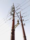 Date: 09/07/19 18:29 Re: Substation electrical question Author: up833 I will guess.. It does at least two things. Probably you have noted that power wires are not attached to poles except at an insulator.Basically the pole just holds up the wire. These are different like a structural connection to hold the line tight.. Secondly I think the configuration is that of a circuit breaker that can be activated by the shaft that runs down the pole and off the bottom of your photo.
RB Edited 1 time(s). Last edit at 09/07/19 18:30 by up833. Date: 09/07/19 18:51 Re: Substation electrical question Author: BRAtkinson I'm neither an electrician nor an electrical engineer. But I agree with UP833 above that it is a manually operated circuit breaker when the rod alongside the pole is turned or moved vertically. Manual circuit breakers are the means by which sections of wire (or overhead on the NEC) can be disconnected from both ends (10 miles or so apart, perhaps?) to allow work to be done to them. While it's possible to work on the wires 'hot', it's far more dangerous to do so and requires heavily insulated platforms/belts/boots to ensure employee safety.
I can clearly make out where each power line is 'tapped' with a small tee fitting to go around the pole via the insulated connectors on some kind of bracket that 'makes' or 'breaks' the circuit when operated via the long rod. It appears that the end of each wire is in a 'Y' shaped connector where the energized wire end sticks out the bottom at an angle and a non-conducting wire/cable goes to the insulator which is connected to another cable attached to the pole. That keeps proper tension on the power conducting wire. What stumps me, though, is what looks like a thin wire (10 ga maybe?) that connects 'further out' than the power takeoff/tap point and then attached to the pole or bracket or the light(?). What's puzzling is that the small wires are not attached to every conductor and that they would seem to be bypassing the insulators presenting full voltage to <whatever>. I'd guess the light goes on if there's some kind of trickle current on the wires? For those interested, next time you're driving along a power line, even a rural power line, for any distance, look at each pole. Every now and then you'll see one with a rod coming down the side to a padlocked 'arm' that can be unlocked and used to disconnect the wires at the top of the pole. Date: 09/07/19 19:15 Re: Substation electrical question Author: sptno I worked for 2 electric utility companies.
These are high voltage switches, manually operate. Looking at these I think they are group operated air break, GOAB. I think that the single smaller wire going down to a wire device is some sort of a power line carrier unit for SCADA. Pat South Austin,TX Date: 09/07/19 19:46 Re: Substation electrical question Author: sparky52t Just wanted to thank all of you for your responses! Very informative!
Date: 09/08/19 05:42 Re: Substation electrical question Author: Buhl56 I think that this is a "disconnect" and not a "circuit breaker".
The difference is that a "circuit breaker" is designed to quickly interrupt fault current and control the resulting arc; but a "disconnect" has to have the voltage and current interrupted and be deenergized while it is opened, to disconnect a section of the line. A "circuit breaker" would be larger, somewhat enclosed, and in a substation. It usually also set up to measure the current, and possibly voltage; in order to interrupt an overload. The insulator segments are typically rated about 25 KVolt. The number of segments estimates the voltage. The tubes under the insulators are probably lightning arrestors that arc to ground. The "Y" shaped connectors connect the mostly aluminum conductor to supporting steel; and allow adjusting the tension and sag. For higher voltage lines, each phase is a "bundle" of two, three, or four conductors spaced in a pattern that reduces the voltage gradient below the air breakdown value. There are weights on each conductor at the left side of the picture. These are to reduce wind driven oscillations in the conductors. Date: 09/08/19 10:24 Re: Substation electrical question Author: 55002 Here in the Uk, they would be called isolators. Generally they are non-load bearing when opening, they would simply destroy themselves by sparking across. Usually we would isolate the circuit (under load) using circuit breakers, then the local isolators are locked open locally for the isolation and earths if needed. However, there's lots of bits I'm not familiar with here. Chris uk.
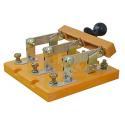
Date: 09/10/19 06:05 Re: Substation electrical question Author: Ray_Murphy It's a high-tech version of this...
 |