| Home | Open Account | Help | 346 users online |
|
Member Login
Discussion
Media SharingHostingLibrarySite Info |
Model Railroading > ST SD40T-2 – Inside the Beast – Phase 5 – Floor CoverDate: 05/10/19 23:50 ST SD40T-2 – Inside the Beast – Phase 5 – Floor Cover Author: tmotor This is Phase 5 of this project. The earlier 4 Phases were posted in previous weeks.
The goal of this Phase is to create a Floor Cover to hide the 4 screw heads and the top of the gear tower. Unfortunately, the floor of the model is even with the upper lip of the grillwork frame. (On the prototype, the floor is level with the walkways.) With one of the grills removed, an unobstructed view of the floor level with respect to the grill frame is clearly seen. The Floor Cover will sit on top of the existing floor, which is already as high as the frames. The edge of the Floor Cover needs to be as thin as possible, to minimize the chance the edges will be visible. A piece of 0.013” tin coated steel (K&S Metals #275) will do the trick. It is thin enough to have a low profile, but thick enough to resist bending and remain flat. The steel core will be attracted to a magnet, which will be used to hold it firmly in-position, yet easily removed. K&S does offer a 0.008” sheet as well, but it was dropped from consideration because it is too pliable. Really liked the thinner edge, but too much risk it would be damaged during normal handling. 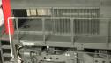 Date: 05/10/19 23:51 Re: ST SD40T-2 – Inside the Beast – Phase 5 – Floor Cover Author: tmotor To create the Floor Cover, a piece 0.718” x 1.550” was cut from the K&S sheet to match the dimensions of the existing floor. Cutting the steel sheet in such a way that it remains flat is a challenge. Tin snips can curl the edges, and/or induce a warp. A bandsaw cuts the thin metal quickly, but be sure to cut it a bit oversize to allow for deburring and fine-tuning the edges.
If there is even a small gap between the saw blade and the bandsaw table, the edge of the thin sheet metal will be curled downward. To prevent this, use a flat piece of scrap Masonite (or plywood) to create a “zero clearance” jig. Merely make a straight cut (an inch or so) in the Masonite, then turn off the saw. Clamp or tape the Masonite in-place. Now the edge of the sheet metal is fully supported and will result in a clean cut. Cutting the Floor Cover from the corner of the sheet provides 2 factory edges that are square. Label the factory edges with an “F”. Do NOT trim these factory edges. Use them as a guideline to keep the opposite side parallel. Dull all of the edges with some sandpaper. Place the Floor Cover on the stock floor. Trim the ends against the walls first, until the fit is loose, but snug. Be careful to keep the ends parallel while trimming. The floor should be able to slip inside the shell without catching on the Floor Cover. The tin plating has a bright finish that is much too smooth for a reliable glue bond. Sand the face-up side with very fine sandpaper to promote glue and paint adhesion. Leave the bottom-side shiny, to help it slide on the existing floor during removal. The worm gear cap was test-fit to the underside of the floor. It was rocked back and forth, but did NOT push the Floor Cover upwards, no mater the position. The disk on top of the worm gear cap remains below the surface of the stock floor, so it does NOT need to be sanded to reduce its height. Edited 3 time(s). Last edit at 05/14/19 09:59 by tmotor. 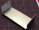 Date: 05/10/19 23:52 Re: ST SD40T-2 – Inside the Beast – Phase 5 – Floor Cover Author: tmotor The Floor Cover needs to be easily removed, yet not rattle around and vibrate during operation. Low-tack glue could be used, but it risks damaging the Floor Cover during removal, or warping it so it won’t lie flat. I have become quite a fan of Neodymium magnets. They are amazingly strong, and come in miniature sizes. The Floor Cover is tin-plated steel, so it will be attracted to these magnets. There is a shallow recess beneath the existing floor. The magnets used are disks, 1mm tall and 4mm in diameter. The eBay seller “heli.porter” has lots of miniature sizes and shapes. They are mounted on the underside with epoxy. (I know for sure the epoxy will hold. It is messy, but the underside of the floor is never seen.) The magnets were mounted so as not to interfere with the movement of the truck during normal operation. Even with a thin layer of glue between the magnet and the underside of the floor, the magnets do not protrude beyond the recessed cavity. The Floor Cover can be slid on and off with ease, so the screw heads are fully accessible for future maintenance. The magnets are so strong that their fields penetrate the plastic and hold the steel Floor Cover securely, yet are invisible.
Merely aligning the sides with the existing floor with the edge of the Floor Cover will give proper fit. Run your fingernail along the side of the stock floor and upward to the Floor Cover edge. It shouldn’t catch on the Floor Cover. The magnets will hold it in-place during re-assembly with the shell. In theory, parts can be soldered to the tinned sheet metal. I have not tried this before, but will attempt to solder brass rod (to represent conduit) to it. I will post the results in Phase 6 of this project. Edited 2 time(s). Last edit at 05/11/19 08:03 by tmotor. 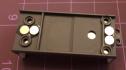 Date: 05/10/19 23:53 Re: ST SD40T-2 – Inside the Beast – Phase 5 – Floor Cover Author: tmotor SIDEBAR: Working with Neodymium magnets.
Trying to use metal tweezers to position the magnets was an exercise in frustration. The magnets do not release cleanly, and will swing around to attach to the metal tweezers. If there is glue on the magnet, there is now glue on the tweezers. Non-magnetic tweezers were used to (in theory) compensate for the magnetic pull. However, “non-magnetic” means they are not going to attract a metal object (such as a screw) or carry a static charge (important when working with electronics). But they are made from stainless steel, and WILL attract these magnets. White ABS tweezers were purchased (Amazon) to eliminate any possibility of magnetic attraction. These worked well. Of course, they are not as durable as stainless steel, so care needs to be taken when using them. However, the tips meet precisely to grip a magnet, and the magnets release cleanly. Having the Floor Cover (or anything else that is a ferrous metal) against the stock floor gives the magnet something to “grab” and will pull it into the glue. Positioning two magnets side-by-side prior to placing them, and moving them as a pair, helped during glue-up. (Placing them individually was fine for the first one, but when the 2nd magnet gets within a country mile of the 1st one it wants to hop onto the 2nd one due to the strong magnetic attraction. The stickiness of the epoxy is not enough to overcome it. Releasing the 2nd magnet next to the 1st has a high probablility it will become an acrobat, jump into the air, and land on the 1st magnet. So, now there are 2 magnets covered with epoxy that need to be removed and separated. Guess how I know this...) The plastic tweezers are also offered in black, but white gives an immediate visual differentiation from the black stainless tweezers. In a pinch, they could be made from Evergreen strips, but for about $1 each it was easier to just order a set with various tip angles. Edited 3 time(s). Last edit at 05/11/19 08:00 by tmotor. 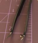 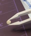 Date: 05/11/19 10:58 Re: ST SD40T-2 – Inside the Beast – Phase 5 – Floor Cover Author: PHall You couldn't punch out some 0.010 styrene to fit the holes? Put some Archer tread plate decal and some paint and it should blend in pretty good.
Much, much less work, but hey, it's your model! Date: 05/11/19 14:47 Re: ST SD40T-2 – Inside the Beast – Phase 5 – Floor Cover Author: ChrisCampi PHall Wrote:
------------------------------------------------------- > You couldn't punch out some 0.010 styrene to fit > the holes? Put some Archer tread plate decal and > some paint and it should blend in pretty good. > Much, much less work, but hey, it's your model! Interesting idea I wouldn’t have thought of. Looking at the OP excellent photos on a previous post I notice the the plate doesn’t run all the way side to side but lends about a foot short on either side. Still, an interesting approach tmotor. |