| Home | Open Account | Help | 247 users online |
|
Member Login
Discussion
Media SharingHostingLibrarySite Info |
Model Railroading > ESU Loksound V5 Rapido board AUX functions questionDate: 12/01/19 10:27 ESU Loksound V5 Rapido board AUX functions question Author: SOU3921 Looking to see if anyone has a diagram for what outputs each of the "X" function pads are on the new Loksound V5 boards. (This is what is in a NS Rapido B36-7) I looked online and couldn't find anything on ESU's site. Nothing in Rapido's manual either.
For example, looking for X2=Aux1, etc..Trying to do this without wiring something to each "X" and just testing. Thanks, Cooper Edited 1 time(s). Last edit at 12/01/19 15:41 by SOU3921. 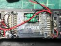 Date: 12/01/19 12:09 Re: ESU Loksound V5 board AUX functions question Author: fbe If you email Matt Hermann at esu here in the states he will get back to you. He does get busy at times so don't expect an overnight response but he is reliable.
Date: 12/01/19 14:05 Re: ESU Loksound V5 board AUX functions question Author: SOU3921 Thanks Matt did email that the board itself is a Rapido product, ESU only makes the decoder.
Cooper Date: 12/01/19 18:11 Re: ESU Loksound V5 board AUX functions question Author: rapidotrains There are three different motherboards used. This is the one for the majority of locos. I hope this helps.
-Jason Date: 12/01/19 18:23 Re: ESU Loksound V5 board AUX functions question Author: SOU3921 Thanks Jason, I am specifically working on an NS and did notice the board was different than my CSX and CR units. I guess there is no way to attach directly to the motherboard, based on that chart. Ditchlights will need to come off the appropriate 21 Pin location with a resistor.
Thanks, Cooper Date: 12/02/19 13:24 Re: ESU Loksound V5 board AUX functions question Author: mmosher The 21 pin connector pinout is available, one source the LS5 pdf manual:
http://www.esu.eu/en/downloads/instruction-manuals/digital-decoders/ Then trace out the pin to the X pads. From the pic above, the Aux 2 output (pin 14, in pic right side, third from bottom) the trace leads to R20 then to X2, since Aux2 output goes to X2 pad, it is likely all the other Xn pads are from AUXn pins on the 21 pin connector, but best to trace it out to be sure. Note FL, RL and Aux 1 & 2 will go thru a resistor to the pad, while Aux 3 and up will to thru a transistor (or perhaps it will be a multi transistor chip, can't tell from pic above since they are on the back side) then a resistor to the pad. Michael Mosher Millville, NJ |