| Home | Open Account | Help | 267 users online |
|
Member Login
Discussion
Media SharingHostingLibrarySite Info |
Model Railroading > 3D Printer (Part 4) – How Does It Do That?Date: 01/24/20 22:06 3D Printer (Part 4) – How Does It Do That? Author: tmotor This is Part 4 of a series on my recent experience with an Anycubic “Photon S” 3D printer. (Parts 1 thru 3 were posted earlier.)
In order to evaluate 3D printers, it helps to have a basic understanding of how a resin 3D printer works. The operation of a 3D printer is actually quite simple. As you know, it builds the part in layers. Each layer is made from hardened resin. The resin is hardened by exposing it to UV light, generated by LEDs. But what determines the shape of each layer? A large LCD screen is the key. The LCD screen makes the magic happen by blocking unwanted UV light from reaching the resin. Just like the LCD screen in a digital watch, it can be told to make a part of the screen black, or leave it clear. When a digital watch needs to display the digit “1”, the appropriate set of points are made black, and the digit “1” appears. The LCD for a 3D printer does the same thing, but instead of digits, it uses the black area as a mask. The UV light is blocked by the black areas of the LCD screen, and the clear areas allow the UV light to pass so it can harden the resin into the next layer. The resin is contained in a Vat, which sits above the LCD screen. The floor of the Vat is a clear plastic FEP (Fluorinated Ethylene Propylene) sheet. Care needs to be taken to not scratch the FEP sheet. (Even a paper towel can create small scratches that “fog” it. I use microfiber towels cut into small 3”x3” squares, then toss them.) If the FEP is scratched, the light will be diffracted, affecting the quality of the printed part. The FEP is a consumable, and will need to be replaced periodically; which is not hard to do, but is time-consuming. It goes without saying that a tear in the FEP would be a disaster. Resin would leak out, go under the LCD screen frame and the coat the printer’s internal components. (Imagine opening your ink jet printer and pouring lots of pancake syrup on the color cartridges.) The printer needs to be disassembled to clean-out the resin before it is exposed to UV light (or sunlight) and hardens. (NOT a fun way to spend an afternoon.) Examine the FEP after each print. If it shows any damage, replace it. There is a threaded rod in the back of the 3D printer, driven by a high precision stepper motor. Attached to the threaded rod is a Build Plate, which travels up and down as the motor rotates. The bottom of the Build Plate is a dead-flat surface, to which the first layers of resin will bond. The Build Plate is lowered and submerged in the resin. After a layer is completed, the Build Plate moves upward about 1/4” to allow more resin to flow between the part and the FEP. Then the Build Plate travels downward and stops short of the FEP, creating a new layer of fresh resin ready to be hardened into the next layer. Edited 2 time(s). Last edit at 01/24/20 22:32 by tmotor. 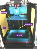 Date: 01/24/20 22:07 Re: 3D Printer (Part 4) – How Does It Do That? Author: tmotor There is a bit of “stickiness” between the FEP and the new layer of freshly hardened resin. When the Build Plate moves upward, the new layer will (hopefully) separate from the FEP. However, if the very first layer of resin is not bonded well to the Build Plate, the part will separate from the Build Plate instead; which causes the print to fail. (Guess how I know this…) When the Build Plate moves upward, the new layer of hardened resin has a choice of sticking to the FEP or the part on the Build Plate. If it chooses to stick to the FEP, Game Over. Trial and error can determine the proper settings for a successful print. After the sweet-spot is discovered, document the settings for that specific resin.
The Build Plate will need to be “leveled”, which is setting the baseline “zero” relative to the FEP. Basically, the Build Plate is carefully lowered until there is a paper-thin space between the LCD screen and the bottom of the Build Plate; then the set screw is tightened. This is done before the first part is ever printed. (If a print fails, try leveling the Build Plate again.) The only thing keeping the Build Plate aligned is a single set screw. One practice I use is to try to NOT hold the Build Plate by the top knob if I can help it. The top knob area is a chunk of metal that is tempting to hold when prying a printed part away from the Build Plate; and lots of videos show this being done. Holding the Build Plate in the air by the top knob area while removing parts exerts lots of torque on the set screw. This is asking for the set screw to slip, moving the Build Plate out of alignment. I place the long edge of the Build Plate onto a paper towel, on a solid surface. Hold the Build Plate by the edges, and force a blade between the Build Plate and printed part to separate them. The energy is transferred to the long edge of the Build Plate, and onto the solid surface. This minimizes the forces experienced by the set screw, which reduces the chance the Build Plate needs to be leveled again. One spec you will see for 3D printers is the Build Volume. This is basically the largest rectangle the printer can produce. The larger the Build Volume, the larger the 3D part you can print. Of course, the larger the Build Volume, the higher the price tag. The work-around for printing parts larger than the Build Volume is to print sections, and then join them. This is relatively easy with 3D CAD software, which allows for test-fitting separate parts together prior to printing them. For example, a DTTX well car is too long to print as a single part (for HO scale) in my printer. So, it needs to be printed in 2 halves, with the joint at the ribs to hide the seam. Edited 6 time(s). Last edit at 01/25/20 11:26 by tmotor. Date: 01/25/20 08:02 Re: 3D Printer (Part 4) – How Does It Do That? Author: sixaxlecentury One of the best tips I have seen, is use some kapton tape and tape the edges of the screen. This way if you get a leak, it wont run down into the internals. I know a few people that this has saved their bacon on.
I keep my entire operation on a lunch tray as well. Date: 01/25/20 08:08 Re: 3D Printer (Part 4) – How Does It Do That? Author: ATSF_Cliff Tmotor:
Not nit picking but the 'threaded rod' is actually a lead screw. These are made with precision threads so that each rotation translate to an identical move. This is most likely an Acme thread lead screw with a simple solid metal follower. Large CNC machines will use a recirculating ball screw where the follower (or 'nut') has balls that follow the thread like a ball bearing. This type of arrangement is quite costly and God help you if you over travel and a ball comes out. Precision metered lubrication is also required for this style. Cliff BTW, Love the series, please keep it up! Cliff Rutherford Grain Valley, MO Edited 1 time(s). Last edit at 01/25/20 08:09 by ATSF_Cliff. Date: 01/25/20 09:49 Re: 3D Printer (Part 4) – How Does It Do That? Author: tmotor sixaxlecentury Wrote:
------------------------------------------------------- > One of the best tips I have seen, is use some > kapton tape and tape the edges of the screen. > This way if you get a leak, it wont run down > into the internals. I know a few people that > this has saved their bacon on. > That is an excellent idea! I have not had a resin leak, but can only imagine it being a total NIGHTMARE. :-0 There is a vinyl "gasket" offered on Amazon that I have ordered to seal the LCD screen. Hopefully it will arrive before I have a resin leak. > I keep my entire operation on a lunch tray as > well. My printer is sitting on an old cookie sheet, but same idea. Similar to the berm around a large storage tank. In case there is a leak, the fluid will be contained. Edited 1 time(s). Last edit at 01/25/20 10:31 by tmotor. 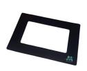 Date: 01/25/20 10:13 Re: 3D Printer (Part 4) – How Does It Do That? Author: tmotor ATSF_Cliff Wrote:
------------------------------------------------------- > Tmotor: > > Not nit picking but the 'threaded rod' is actually > a lead screw. These are made with precision > threads so that each rotation translate to an > identical move. This is most likely an Acme > thread lead screw with a simple solid metal > follower. Cliff, you are correct. "Acme thead lead screw" is a much more accurate description. A machine screw has angled threads that are designed to bind to tigthen onto the nut. An Acme thead has "flat" sides, so it pushes against the nut with minimal friction. > BTW, Love the series, please keep it up! Glad you are enjoying it. ;-D I have only had the printer for less than a month, but have made my share of discoveries and rookie errors. For those that have a 3D printer already, my observations will be old news. However, for those that are investigating a future purchase, or are just interested in the technology, I hope the series will be of some benefit. Date: 01/25/20 18:18 Re: 3D Printer (Part 4) – How Does It Do That? Author: tmotor 4thDistrict Wrote:
------------------------------------------------------- > I have also found that the less expensive > replacement FEP sheets available on Amazon and > elsewhere are not as durable as the OEM sheets. > They more easily become abraded, especially when > multiple prints of the same item are made. The > more expensive sheets are more durable. Good to know. Some of the Amazon FEP sheets are thinner, which some believe to increase part resolution. However, thinner does most likely mean less durable as well. Did you notice any difference in the resolution of the parts with the Amazon FEP? > I also > learned to print items other than always at the > center of the tray. Varying the position to near > the ends or sides prevents the FEP from wearing > out in the same places. Moving the prints around > spreads the wear, resulting in fewer FEB changes > being necessary. TERRIFIC good idea! Thanks for sharing. Date: 01/26/20 08:50 Re: 3D Printer (Part 4) – How Does It Do That? Author: chessie2101 Fantastic series. You’ve done a super job at explaining the technology clearly. Thanks for taking the time to post!
Posted from iPhone Jared Hamilton Scott Depot, WV Date: 01/26/20 15:44 Re: 3D Printer (Part 4) – How Does It Do That? Author: tmotor 4thDistrict Wrote:
------------------------------------------------------- > No. The resolution appears to be the same. I would > think that a new, clear sheet would not affect > resolution until it begins to wear and looses > transparency preventing the UV light from passing > through it cleanly - which from my experience will > happen sooner with less expensive sheets. The > cheaper sheets seem less durable. Makes sense the light will pass thru the FEP fine as long as it is clear, regardless of thickness. I'm with you. I will look for the more durable (thicker) FEP replacements. ;-) |