| Home | Open Account | Help | 228 users online |
|
Member Login
Discussion
Media SharingHostingLibrarySite Info |
Model Railroading > 3D Printer (Part 10) – Slicer SoftwareDate: 02/07/20 10:29 3D Printer (Part 10) – Slicer Software Author: tmotor This is Part 10 of a series on my recent experience with an Anycubic “Photon S” 3D printer. (Parts 1 thru 9 were posted earlier.)
After the geometry of the part is created in the 3D software, it is exported as an STL file. Launch the Slicer software, and open that STL file. These are some functions of Slicer software: Slicing Parts As the name implies, the slicer software will slice the 3D part into layers. The layer thickness can be varied. Thicker layers = faster printing, but generally less resolution. Sometimes this is given in microns (1000 microns = 1mm). The Photon Workshop defaults to 50 microns (0.00196”), which is the thickness of sheet of paper. The Photon S has a resolution of 47 microns, so going much smaller than 50 microns won’t show up in the part. (Some resin printers are capable of 25 microns, and are priced accordingly.) Exposure Times Tune this to the specific resins being used. There are a few spreadsheets online that list different resins along with the settings other users have found work for them. The resin manufacturers will also have recommendations. These are a good starting point. If a portion of the part is deformed, then increase the Exposure Time to make the resin more rigid to resist warping. A typical exposure time is 8 seconds per layer. (If that doesn't work, add a Support.) First Layer(s) Exposure Time The first few layers need to bond to the Build Plate, or the new layer of resin stays attached to the FEP; which is the dreaded Failed Print. Even if the first few layers do bond, during the building of the part the they may pull away from the Build Plate before the print is completed; again a Failed Print. Longer exposure times can help form a stronger bond of these layers to the Build Plate. The number of First Layers can be as few as 1, or as many as 40+. A typical exposure time is 60 seconds per layer. (For the rest of the layers the shorter 8 second exposure time is used.) If it takes a jackhammer to separate the part from the Build Plate, reduce the number of First Layers, and/or the exposure time. Refer to the resin spreadsheets for suggested settings. Supports These are analogous to scaffolding erected around a structure to make sure it will stay true, and not fall over during construction. The Supports are placed at points on the part where the small contact area will be the least noticeable (similar to the gate that connects a part to a sprue for an injection molded part). The more Supports there are, the better the chance of a successful print. However, the price paid is there will be a lot of Supports to be removed, and each one will contact the part; increasing the risk of damaging the part (by leaving a small crater, or a small nub) during removal, requiring more post processing of the part. Supports are made from resin. More Supports = more resin. Since the Supports are discarded after the part is printed, it doesn’t make sense to have a bazillion Supports just for insurance. The first successful part I printed had more resin consumed in the Supports than the actual part itself. The 2nd time that part was printed, I throttled-back and only used 50% of the supports. The part printed fine. I also reduce the Contact Area of the Support and the part. This allowed removal of the Supports by twisting the part, vs. using a sprue cutter for each Support. It also left a much smaller nub on the printed part = less clean-up. Look for the low spots on the part, and add a Support there. When a layer forms, it needs to attach to something, either the part or a Support. Otherwise, the layer will form, but never be incorporated into the part being printed. For example, when the leading edge of the part begins to form, it will need to have a Support (or a series of them) already in position to act as an attachment point. Otherwise the layer will become an “island”, and stay attached to the FEP. There is a whole art to adding Supports, much of it is trial and error. It is beyond the scope of this thread to explain everything, but search for “3D Supports” to find many good tutorials. ChiTuBox I don’t have experience with other slicer software, but from what I understand one of the most popular is ChiTuBox, which is available for free. It has been around a while, and has lots of features. It can generate a file with a PHOTON file extension, which used to be compatible with Photon printers. However, after the latest firmware update from Anycubic, the PHOTON file extension is no longer compatible with Photon S 3D printers. (The work-around is to load an earlier version of the firmware.) ChiTuBox users have repeatedly asked for it to be modified to generate a PWS file format. But until Anycubic shares the file format specs, ChiTuBox will not be compatible with the Photon S printer. Many 3D printer manufacturers decided to be compatible with ChiTuBox, so they did not have to reinvent the wheel by developing, and then supporting, their own version of slicer software. However, Anycubic decided to have a proprietary slicer file format. Will they share the specs with ChiTuBox? Time will tell. Snapshot Once the Supports are added, save it as a new STL file to create a snapshot. This way it can be used to fine-tune the Supports later. Initially, I thought after the Supports were added the STL file was now ready for the printer. Nope, that is a Rookie Error. An STL file won't even appear as a choice to print on the LCD screen. (Changing the file extension from STL to PWS gets the file to appear on the LCD screen, but generates an error message when attempting to start the print.) The Slicer button now needs to be pressed to slice the STL file (with the Supports) into a PWS file, to be in a format the Photon S printer understands. The file will now appear on the LCD screen, and the part can be printed. If the printed part needs more Supports, or existing Supports need to be relocated, attempting to open the PWS file as the baseline won’t work. The STL file that was saved as a snapshot (prior to creating the PWS from it) needs to be opened instead. Keep the STL and PWS as a pair. Give them the same file name, with the file extensions being STL and PWS. Edited 4 time(s). Last edit at 02/07/20 15:53 by tmotor. 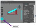 Date: 02/08/20 13:50 Re: 3D Printer (Part 10) – Slicer Software Author: funnelfan When it comes to supports, how long of a freespan should youn have between supports? Let's say I have a 24" long grab iron, which is a bit over a quarter inch long in HO scale. How many supports would in need between the two ends?
Ted Curphey Ontario, OR Date: 02/08/20 19:41 Re: 3D Printer (Part 10) – Slicer Software Author: sixaxlecentury Is it freestanding, or "molded on" so to stay? I would shy away from having grabs where wire could be used.
Date: 02/09/20 22:53 Re: 3D Printer (Part 10) – Slicer Software Author: tmotor funnelfan Wrote:
------------------------------------------------------- > When it comes to supports, how long of a freespan > should youn have between supports? Let's say I > have a 24" long grab iron, which is a bit over a > quarter inch long in HO scale. How many supports > would in need between the two ends? Technically, a Support can be put just about anywhere. However, the trick is to have the Support attach to an area of the part that will not cause damage when the Support is removed. A grab iron is quite fragile, so attaching a Support to a grab iron would require a significant amount of care to remove it. Though I have not experimented with small diameter resin, odds are pretty high a resin grab iron will be susceptible to damage. As far as Supports in general, a matrix of about one about every inch or so seems to be enough. sixaxlecentury Wrote: ------------------------------------------------------- > I would shy away from having grabs where wire could > be used. Good advice. Theoretically, the mounting holes could be designed into the part, so a wire grab iron could be inserted and glued in-place. |