| Home | Open Account | Help | 341 users online |
|
Member Login
Discussion
Media SharingHostingLibrarySite Info |
Model Railroading > 3D Printer (Part 11) – SupportsDate: 02/11/20 22:55 3D Printer (Part 11) – Supports Author: tmotor This is Part 11 of a series on my recent experience with an Anycubic “Photon S” 3D printer. (Parts 1 thru 10 were posted earlier.)
The Slicer software’s main purpose is to slice the 3D part into layers. However prior to pushing the Slicer button, Supports need to already be in-place. The majority of the time spent using the Slicer software will be attaching, moving, deleting, and editing Supports. Upside-Down The view of the part in the Slicer software will be built from the bottom of the screen, going toward the top. However, when the part is being printed, it will be inverted relative to the screen image. This takes a little getting used to, as we tend to expect things to build in the same orientation as shown in the Slicer software image. (It helps me to only think in terms of the layers that build from the bottom of the screen to the top, and let the printer worry about inverting it during the actual printing process.) Contact Area The attachment point of the Support to the part is the Contact Area. The default is a pretty large area, which required sprue cutters to remove the Supports. Rather than a few Supports with large Contact Areas, it seems to be better to have more Supports with smaller Contact Areas. Of course, if made too small, the Contact Area will not be strong enough to withstand the upward force of the Build Plate as it peels the new layer of resin away from the FEP. If a few Contact Areas fail, the adjacent ones will usually be able to pickup the slack. However, if there is any flex to the part, unwanted movement could distort the part. If enough Contact Areas fail, the entire part will fail. The Matrix A general guideline is to have a Support every inch or so, in a matrix pattern. However, this will vary based on the part’s shape. The purpose is to provide enough Supports to ensure the part stays attached to the Build Plate. If the number of Supports contacting the part is to be minimized, Supports can be attached to existing Supports for additional adhesion to the Build Plate. Experiment with what works best. Islands When printing a part, the leading edges of the part need to “grow” from a Support. For example, consider the image of a simple (upside-down) mountain range shape. Each peak needs to have a Support, otherwise the resin for the peak will form on the FEP, but nothing will be attached to it. When the Build Plate rises, the resin stays on the FEP creating an island of orphaned resin. This results in a failed part. Have a Support at each peak, and the part will print successfully. Consider the 3 images of the cannon. The left-most image shows what happens when the front of the barrel is not given any Supports. It will “grow” from the nearest Support, but the print will fail. In the middle image the barrel is fine, but the perimeter of the wheel is deformed. After adding more Supports to the wheel tread, the right-most image shows the resulting part. Edited 1 time(s). Last edit at 02/12/20 14:41 by tmotor. Date: 02/11/20 22:56 Re: 3D Printer (Part 11) – Supports Author: tmotor Bases
The bottom of each Support has a large ½” x ½” plate that provides a large area of attachment to the Build Plate. The shape of this Base can be modified (square, hexagon, etc) depending on the options in the Slicer software. Generally, the Supports are close enough that the Bases intersect and join into a large solid plate. Rafts One option for a Base is to have a large plate beneath the entire part. Instead of a bunch of ½” x ½” Bases, a huge Base (say 3” x 4”) known as a Raft. This provides a large area of attachment to the Build Plate. For instances where there are few Supports, this is a good option to provide the maximum adhesion to the Build Plate. Skates After the part is printed, it needs to be removed from the Build Plate. The Base of each Support is attached to the Build Plate. A metal blade (knife, spatula, etc.) is used to break the bond between the Support Base and the Build Plate. In order to help guide the knife edge under the Base, the perimeter has a beveled edge which is like the profile of the blade on a pair of skates. (There are other perimeter profiles available for the Base that are more blunt, but I stick with the skate profile.) Since the bevel is around the entire perimeter of all Bases, the skate will assist the blade to get underneath the Base regardless of the direction. Filament vs. Resin Supports By now most have had a look at filament 3D printers. One of the main differences in the Supports is the Filament printers have the ability to change the material mid-print, so their Supports could be built from a material that can be dissolved-away. This was particularly advantageous for internal voids that required Supports. However, resin printers can only use the resin in the Vat as a building material, so it is not possible to change materials. This means the internal Supports need to be as small as possible, and then be physically removed after the part is printed. Edited 1 time(s). Last edit at 02/11/20 22:58 by tmotor. 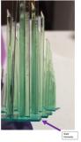 |