| Home | Open Account | Help | 297 users online |
|
Member Login
Discussion
Media SharingHostingLibrarySite Info |
Model Railroading > Lift out section at doorway.Date: 11/14/20 15:48 Lift out section at doorway. Author: WrongWayMurphy I found a couple beat up Lionel or similar bridges, screwed them to a piece of 3/4" plywood, and
installed 5/16" lag screws on each end to form a lift out bridge in front of the shed doorway entrance. Wing nuts tightened on the lag screws hold the ends in place. Unscrew them and the bridge lifts out. The installation is complicated by the fact that this bridge is an a curve. Soon I will put track on the bridge and install track on the bench work to mate to the bridge. Not sure if this will be a permanent solution but it seems to work for now, and it is simple. I try to build according to the KISS principle, though I am duly impressed by more sophisticated engineering solutions to problem solving. I typically host op sessions once a month so this will normally only be installed for these monthly events, and sitting on a shelf otherwise. If you have better solutions, I would like to know about them. Edited 1 time(s). Last edit at 11/14/20 15:53 by WrongWayMurphy. 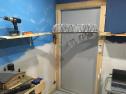 Date: 11/14/20 16:08 Re: Lift out section at doorway. Author: tomstp Wheres the sign that says "DUCK DAMN IT"?
Date: 11/14/20 20:18 Re: Lift out section at doorway. Author: Kimball Do you mean "carriage bolts", not "lag screws"? Lag screws as I know them do not have machine screw threads, they are just big wood screws with hex heads. I enjoy all your posts, BTW.
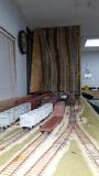
Date: 11/14/20 20:40 Re: Lift out section at doorway. Author: SP4360 This was my solution to getting past the door of my Fubar Flats yard. I through the KISS plan out the window with this one, straight track, curved track and a wye switch cut in half. Oh, and semaphore signals at the end of the siding. I built a small scale model of the lift section to determine where the actual "hinge" would be, then used 4" 4 hole straps for the hinges. The "free" end sets on a 1x4 ledge and drops onto a dowel pin. All tracks can take a train at speed whether pulling or pushing without piling up. There is rougly a 1/16th" gap at eith end of the rails on the lift section. Boilingman did a small feature on the layout a year or so ago and called this the "Duck-beater"
 Date: 11/15/20 05:37 Re: Lift out section at doorway. Author: WrongWayMurphy Kimball Wrote:
------------------------------------------------------- > Do you mean "carriage bolts", not "lag screws"? > Lag screws as I know them do not have machine > screw threads, they are just big wood screws with > hex heads. I enjoy all your posts, BTW. Yes, carriage bolts is the proper term. A wing nut would thread rather forcibly onto a lag screw. Date: 11/15/20 09:08 Re: Lift out section at doorway. Author: PHall Waiting for the photo of when you forgot to duck, because you know it's going to happen.
Date: 11/15/20 09:47 Re: Lift out section at doorway. Author: inyosub I have a similar thing where I have a single track that bridges a doorway. The Way my layout is setup this reaches
an Island of switching so does not need be up all the time. What I did was hing it to swing -down-! This way when you lift up you have stops, alignment blocks and stops and the rail are just just gaped and chamfered. Works great. The one disadvantage is you can't really put anything on it. You could (I didn't ) put a deck bridge on with a fabricated substructure; but anything that sticks up, like your truss bridges; would be 'at risk' of being bumped by a passing person. You could could build a protective pocket but now it's getting way complicated. I mainly just wanted to drop the idea that a track that swings down has many advantages. Rather than swinging up. Date: 11/15/20 10:26 Re: Lift out section at doorway. Author: SP4360 While wiring the layout I had more than one Maxwell Smart "missed it by that much" moments getting out from under it. but not at the Duck Beater. I also have 2 reed switches that kill the yard and main track throttles when it's in the up position.
PHall Wrote: ------------------------------------------------------- > Waiting for the photo of when you forgot to duck, > because you know it's going to happen. Date: 11/15/20 12:34 Re: Lift out section at doorway. Author: NCA1022 OK I'm gonna try to post some photos here of a permanently attached lift bridge I built that worked pretty well. This bridge spanned the entryway into the bedroom where I built my 10 x 13 layout. The room had a short (about 4 foot) entryway which went past the closet. I built the layout in to the closet, so the track punched thru the closet wall, swung over the entryway and connected to track along the wall. The bridge was made out of plywood. Actually two pieces of plywood spliced together with drywalll screws and wood glue for a solid joint.
1: Bridge lowered in place. Photo taken from the Goodyear blimp. Well, OK, me on a short ladder... 2. Bridge in the raised position. I used a piano hinge to attach the moveable bridge to to wall. I went with a piano hinge because it provided both a solid attachment and there was virtually no "slop" in the hinge. This helped to keep the tracks aligned properly. 3. Bridge retainer (aka "sky hook"). A simple hook and eye kept the bridge up and out of the way when trains weren't running. In photo two you can see the wiring that went to the bridge tracks. I used stranded wire and created a 360-degree loop in the wires about 1/2" in diameter, sort of like a spring. I kept the wire right next to the hinge. This provided plenty of wire slack and allowed for the small bit of movement needed between the raised and lowered positions. Edited 3 time(s). Last edit at 11/15/20 18:12 by NCA1022. 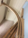 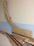 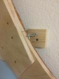 Date: 11/15/20 13:28 Re: Lift out section at doorway. Author: NCA1022 More bridge photos.
4: This is the free end of the bridge where it meets the trackage exiting the closet, pictured here when it is not quite fully closed. I built a small ledge for it to rest on. To maintain track alignment, when the bridge was completely down I drilled a 1/4" hole thru the bridge and into the shelf and then glued a short piece of 1/4" dowel in the hole in the bridge. This indexed the free end to always align it in the exact same place. If you look closely you can see the dowel about to go into the indexing hole on the shelf. The photo shows a sliding cylinder-style latch to keep it in place. In practice I found the latch wasn't really needed for running trains. The bridge stays down and aligned without it. It was more of a safety measure during op sessions to keep the bridge from being disturbed if somebody mis-judged their nod-under while a train was passing overhead. 5. Closet end of the bridge, showing how I maintained track alignment across the bridge. Once the carpentry was done, I prepared the flex track sections that would be spanning the bridge joints. I had seen this technique used on another layout somewhere and though it was a good way to hold the track in alignment. First step was to measure where the flex track was going the span the bridge joint and then remove a couple of ties on either side of the joint. Then I temporarily pinned the track in place and measured where the rails were located. Next I removed the flex track and installed flat head brass wood screws under each rail, one on either side of the bridge joint. I adjusted the height of the screws so that the screw head just touched the rails when the track was in place. Then I laid the flex track. I used adhesive caulk which forms a solid grip on the ties and keeps the track exactly where it needed to be. When the caulk had dried, I soldered the rails to wood screws. Final step was to use a cut-off disk in the Dremel tool and cut the gaps. A few passes with a fine file to remove sharp edges on the rails and I was done. I used the same approach on the hinged end of the bridge too. I micro-adjusted the vertical track alignment by gluing a card stock shim between the bridge and the shelf. This bridge worked out really well. I could easily lift it up and out of the way when it wasn't needed and it drop it back down when it was time to run trains For the 2 years this bridge was in service, there were no derailments due to mis-alignment and I didn't need to adjust anything. Benchwork height for this track was about 60", making the bridge high enough that I could duck under pretty easily. Not quite a "nod-under" (I'm 6'1") but waaay easier than a hands and knees crawl-under. Alas, this layout no longer exists. It came down in 2015 when we moved out of this house. I only had the layout running for a couple of years and really liked it. So in our current house I decided to reconstruct the same layout again, this time in a 10x13 room but without the entryway. So I'm now doing some detailed benchwork design to build another hinged lift-up bridge, just like this one. I wonder: Have any other model railroaders built the same basic layout design twice? Hope this was helpful. - Norm Edited 2 time(s). Last edit at 11/15/20 18:17 by NCA1022. 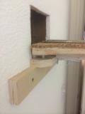 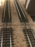 Date: 11/16/20 02:39 Re: Lift out section at doorway. Author: z4driver For those contemplating lift outs etc, you might be interesed in this new product. I haven't tried it but it does seem as though it could be useful.
https://youtu.be/OEzAf3_6egw Lee |