| Home | Open Account | Help | 313 users online |
|
Member Login
Discussion
Media SharingHostingLibrarySite Info |
Model Railroading > BNSF 72’ Frostline Reefer (CAD 6) – ClampsDate: 03/09/23 00:00 BNSF 72’ Frostline Reefer (CAD 6) – Clamps Author: tmotor This is CAD 6 of a series on generating the CAD geometry for the BNSF 72’ Frostline Reefer project.
CAD 1 thru 5 of this series was posted earlier. Work continues on the Plug Door… The Lock Rods are mounted to the Ribs with Clamps. Initially I thought the Clamps were large castings, but upon closer inspection it is clear they are metal stampings. There are 8 Clamps needed to secure the Lock Rods. Plus there is the FRA mandated Safety Arm mounted to the upper horizontal Rib, which makes 9 Clamps. To save time, one Clamp was created in a separate drawing. It can then be copied and imported into the main drawing as an Assembly. It can be moved around and positioned where needed, but the shape can’t be changed. Weld Beads A pair of nuts is used to mount each Clamp to a Rib, but they are also welded in-place. This seems a bit redundant. Were the Clamps slipping out of alignment? At first I thought the welds were added after initial delivery, to correct a problem. However, I checked images of brand new BNSF Reefers taken in 2002 and the weld beads are there with fresh paint on them. So why were the weld beads applied at the factory? My assumption is the nuts are used to initially mount the Clamps to the Ribs. The holes in the Clamps are large enough to allow some play, and the Clamps are fine-tuned to be square to the Lock Rod. (This reduces any binding, which would make opening the door difficult, as well as add unnecessary wear and tear.) Once the Clamp position is to be made final, a weld bead is applied to each side, permanently mounting it to the Rib. If the Clamp needs to be removed, the weld beads can be hit with a grinder (being careful to not remove too much of the Rib). After the replacement Clamp’s alignment is confirmed, new beads can once again weld the Clamp in-place. MIG A weld bead has a distinctive shape. The type of torch that made it can generally be determined by the shape and the application. The metal components are about 1/8” thick, and manufacturers want to spend as little time as possible making the weld. The weld beads look almost like a bead of caulking. Most likely these are MIG (Metal Inert Gas) welds, which is a relatively quick process. (A wire is continuously feed to the tip of the gun. The wire is electrified and becomes the “electrode” and melts into the weld puddle when it comes in contact with the metal components.) Because it is a manual process, the weld beads lack the straight-line precision of a robot weld. This means they will be “lumpy” and wander a bit. Simulating these “organic” shapes can be a real trick with CAD. Modeling Weld Beads Fortunately, there is a Mesh feature that allows a framework of the basic cylinder-shape to be modified. In order to avoid the Cookie-Cutter look, the weld beads are all different. Rather than have the weld beads be a separate component, they were made part of the Clamp Assembly. 5 Clamps were given unique weld beads. In order to have all 9 Clamps look different, 4 of the Clamps will be flipped 180-degrees (to differentiate them from the non-flipped Clamps). I considered having the weld beads unique on every Plug Door, but decided it would be an extra layer of complexity for (perhaps) a Phase 2 down the road. The welds are quite small, and most folks won’t notice. As long as they are there, I’m happy with it. I also considered not having the weld beads at all, but for a little more effort it is worth knowing they are there. Moreover, the Plug Doors I will be doing next are the ones with exterior insulation, and they have LOTS of visible weld beads. These small weld beads are a warm-up for creating the much longer weld beads needed to attach the sheet metal that protects the exterior insulation. Beyond RTR ExactRail provided the inspiration for the weld beads. They did a great job on the stitch welds on the Plug Door for their 64’ Reefer. Under high magnification, each weld bead looks unique. (They probably made 10 unique weld beads and used them randomly.) However, one area that could use some improvement is the Clamps. They did have the Lock Rods as a separate part, but did NOT have them inset into the Ribs. They sit on the face of the Ribs. The Clamps on the prototype are slightly wider than the Ribs, so there is some overhang. Of course, for the Clamps to be molded onto the face of the Ribs, this overhang is not possible with injection molding. (However, if the Clamp were molded with the Lock Rods, then it could be applied over the Rib with the appropriate overhang.) Instead, the Clamps are barely noticeable. It would have helped if the Lock Rods had a collar molded into them at each Clamp position. However, the Rib spacing is NOT symmetrical, so there is a 50% chance the Lock Rod will be installed upside-down. To simplify assembly, the Lock Rods were made with smooth sides. I’m sure there were some discussions about how to cut production costs, and this is the result. Most folks (including me) that evaluated those reefers were merely looking for separately applied Lock Rods and gave them full points. It is satisfying to be able to add the proper Clamp detail to the Plug Doors, so they are a prominent component like the prototype. The weld beads along the sides are the cherry on top. :-D Dave Edited 3 time(s). Last edit at 03/09/23 09:11 by tmotor. 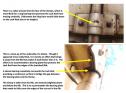 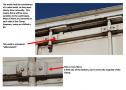 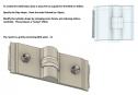 |