| Home | Open Account | Help | 301 users online |
|
Member Login
Discussion
Media SharingHostingLibrarySite Info |
Model Railroading > BNSF 72’ Frostline Reefer (CAD 7) – Lock RodsDate: 03/13/23 06:13 BNSF 72’ Frostline Reefer (CAD 7) – Lock Rods Author: tmotor This is CAD 7 of a series on generating the CAD geometry for the BNSF 72’ Frostline Reefer project.
CAD 1 thru 6 of this series was posted earlier. Work continues on the Plug Door… In order to slide a Plug Door (along the side of the car), it needs to move several inches away from the car. The pivot point for the Plug Door to swing upon is provided by large vertical Lock Rods. A pair of them runs the entire height of the Plug Door. One-Piece Construction Because there are different diameters of cylinders telescoped within each other, I had assumed there were Door Rods that rotated within the vertical Tubes. However, after looking closely at the welds, it appears there is a solid connection along the entire Lock Rod. Though the Lock Rods are built from telescoped tubes, they are welded to form a single part. This strongly suggest the entire vertical Lock Rod assembly rotates within the Clamp. This video shows a Plug Door being opened: (Need to cut-n-paste this into your browser. You know the drill…) youtube.com/watch?v=fl_9m_pSqes I closely watched the rust and grime spots on the Lock Rods. They did rotate as the door swung away from the door frame. This confirms the entire vertical Lock Rod assembly rotates as a single piece. Edited 1 time(s). Last edit at 03/13/23 06:30 by tmotor. 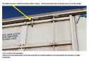 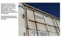 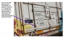 Date: 03/13/23 06:14 Re: BNSF 72’ Frostline Reefer (CAD 7) – Lock Rods Author: tmotor Spring Into Action
At the bottom of each Lock Rod is a Spring. Its job is to keep the Plug Door away from the car when it is in the open position. Without the Spring, when the Plug Door is shoved along the Rail to open it, there would be nothing to keep the inside of the Plug Door from scraping against the outside of the car. To create the body of the Spring, I had to become familiar with the Coil command. The interface recently changed, so using older tutorials initially confused me. However, once I realized the issue, I found a recent tutorial and was impressed with the capabilities. The number of coils can be specified, pitch, rotation, and diameter. Back in the day, CAD required all sorts of gyrations (algorithms, macros, etc.) to create a coil-shape. It is nice to have a command that is parameter driven instead. :-D Dave Edited 1 time(s). Last edit at 03/13/23 06:22 by tmotor. 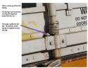 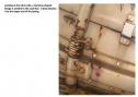 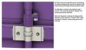 |