| Home | Open Account | Help | 333 users online |
|
Member Login
Discussion
Media SharingHostingLibrarySite Info |
Model Railroading > BNSF 72’ Frostline Reefer (CAD 9) – Welded NutsDate: 03/22/23 00:00 BNSF 72’ Frostline Reefer (CAD 9) – Welded Nuts Author: tmotor This is CAD 9 of a series on generating the CAD geometry for the BNSF 72’ Frostline Reefer project.
CAD 1 thru 8 of this series was posted earlier. Work continues on the Plug Door… The cylinder of the Turnbuckle has a hex nut welded to each end. The initial geometry had the hex nuts butted-up against the ends of the cylinder, but no weld geometry. Though most folks would just call it good, it bothered me that the weld was “missing”. So, I set about creating the geometry for these welds. Though the concept was simple, getting CAD to generate it was easier said than done. Orbital Welds When the Turnbuckle was welded together at the YSD (Youngstown Steel Door) shop, the cylinder and nuts were put in a jig. They were tack-welded so they stayed in-place. Then it was mounted in an Orbital Welder, which looks like a modified lathe. Jaws clamp onto the cylinder and a torch is lined-up with the joint. The torch applies a bead, as the cylinder is slowly rotated. The timing needs to be in-sync between the wire being fed to the weld puddle by the torch, and the speed of rotation. Once these speeds are fine-tuned, good welds can be consistently produced. After one end is done, the jaws are released, the Turnbuckle is spun 180-degrees, reclamped, and the other end is welded. Lofty Goals A few different attempts were needed to create the geometry. The Form feature worked well for the MIG weld on the Clamps, so initially a stand-alone Form was used. Unfortunately the transition from the nut to the weld had a ridge line. It looked like it was “glued-on”, instead of being smooth.. However, on the Plus Side, where the Form met the cylinder was smooth, since they were the same diameter. The Loft command would create a smooth transition between the hex nut and cylinder, but too smooth. The geometry generated by the Loft command is “too perfect” to represent a weld. What was needed was a mulit-layer approach. Edited 3 time(s). Last edit at 03/22/23 11:03 by tmotor. 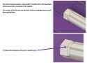 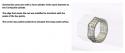 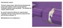 Date: 03/22/23 00:00 Re: BNSF 72’ Frostline Reefer (CAD 9) – Welded Nuts Author: tmotor Mirror, Mirror I discovered some limitations of the Mirror command. Though using the Mirror command saves time by making a copy of components, it will only copy certain types of components. One type of component that it will NOT copy is a Form. (Dhoooo!!) Time for Plan B. Instead of Mirroring all of the geometry, just the basic shapes will be Mirrored. The complex Welded Nut geometry will be created as a separate part, and then imported as a copy. (This is similar to the method used for the Clamps.) The hex nut and the weld bead will be a single part. After being attached to the main geometry, the nut is rotated slightly in order to avoid a “cookie cutter” look (where all of the flats of all the nuts have the same orientation). Don’t Bug Me Not to throw the Mirror command under the bus a 2nd time, but… The Round-over, Fillet, and Chamfer are used routinely when creating geometry. When attempting a Mirror, if I select a Round-Over (or Filler or Chamfer), it can be highlighted (prior to being Mirrored), but does not appear in the copy (after performing the Mirror). No warning or error message is given. Looking on the Fusion 360 Forum, it appears this was reported as a bug in 2017. 6 years later it still doesn’t work, so I’m going to assume it won’t work any time soon. Just take a screenshot of the parameters of those features on the original, and redo them on the Mirrored copy. Though this is a disappointment, it certainly beats having to make a copy of EVERYTHING from scratch. It doesn’t take that much time to recreate those features. What does take time is assuming those features are not appearing because I made yet another Rookie Error. These features (Round-over, Fillet, or Chamfer) are pretty much standard on most components, so surely this should work fine, right? I looked high and low for the Magic Button to press to have those features appear. Nothing I tried worked. Turns-out it is a known bug. :-0 Having to back-track and redo geometry is an occupational hazard of learning CAD. Thank goodness for YouTube tutorials and the Fusion 360 Forum for providing a reality check that I’m not losing my mind. Side-stepping insanity helps keep me on the right track, allowing the project to incrementally move forward. I spent the better part of a week working on this geometry, and the only thing I have to show for it are 4 dinky weld beads that (most likely) no one will ever notice. However, I did become much more familiar with the Form and Mirror features, which will come in VERY handy in the near future. Dave Edited 1 time(s). Last edit at 03/22/23 00:02 by tmotor.  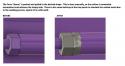 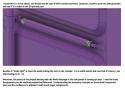 |