| Home | Open Account | Help | 258 users online |
|
Member Login
Discussion
Media SharingHostingLibrarySite Info |
Steam & Excursion > PRR S2 TurbineDate: 08/14/11 20:19 PRR S2 Turbine Author: Panamerican99 PRR's S2 in a publicity photo with the description that was attached. It didn't last very long.
- JH 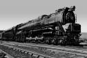 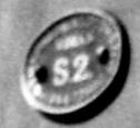 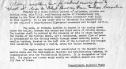 Date: 08/14/11 21:16 Re: PRR S2 Turbine Author: Harlock Lasted about as long as the UP / GE steam turbines :) Thanks for the pic.
Mike Massee Tehachapi, CA Photography, Railroading and more.. Date: 08/15/11 01:22 Re: PRR S2 Turbine Author: john1082 Would really like to read some stories from PRR engineers and tech guys from the post-war era that could reveal their inner thoughts re S-2, T-1, etc.
John Gezelius Tustin, CA Date: 08/15/11 05:34 Re: PRR S2 Turbine Author: juicejunkie Great shot Jim. I had the Lionel version but I never cared for the way they looked; something about esthetics I think.
Jack Bejna Los Angeles, CA Date: 08/15/11 07:39 Re: PRR S2 Turbine Author: YankeeDog Imagine what that front number plate would be worth today. One of a kind.
Date: 08/15/11 17:04 Re: PRR S2 Turbine Author: timz2 Why did it need a clutch?
Date: 08/15/11 18:39 Re: PRR S2 Turbine Author: wcamp1472 Pure guessing here,
But there is engineering practice that may apply. The current practice used on most EMD diesel turbocharged engines uses a 'trapped ball' form of uni-directional, overrunning clutch. In EMD's case, the turbine shaft/compressor must be driven by the diesel engine's camshaft gear train ---- there is a spur gear train that spins the turbo shaft in order to provide positive air pressure to the engine before there is enough exhaust heat to spin up the turbo shaft. Once the engine load has gotten the exhaust temperature hot enough, the turbine shaft rapidly speeds up, exceeding the drive speed from the gear train. The 'clutch' is actually a series of rectangular 'boxes' machined into the hub of the turbine shaft. The outer edge of the box is tilted at a modest angle. Inside each cavity is a steel ball --- the driven gear spins around the slower speed turbo shaft. The gear hubs wedge shaped boxes force the steel balls onto the turbine shaft, locking the gear and shaft together -- thus providing the necessary speed to the intake air compressor to allow the engine to run. Typically up through throttle 6. When the diesel engine is being run a low exhaust heat, the turbine compressor pressurizes the engines 'air box' (engine air intake system) to about 6 PSI. Hopefully, with a heavy enough load, the engin'e exhaust heats up and now begins to spin the turbine blades, the turbine shaft and the compressor -- now she goes to work! As the turbine speeds up the shaft rotative speed soon surpasses the engine driven gear's hub speed and the the trapped wedge balls (in the hub) are soon moved to the wider space of the wedge box and there they are disconnected from the high speed turbine shaft -- the engine's output now increases by about 100^%! So the shaft 'clutch' is automatic, depends on the drive gears speed to be higher than the shaft's speed and when needed the clutch balls again lock onto the compressor shaft ---continuing the fresh air supercharger boost. NOW... back to PRR's S2 steam turbine. You would want a clutch, of the overrunning type, to disconnect the reverse turbine's drive shaft while running forward --- saves reverse turbine's shaft bearings, etc. Both turbines drove the same primary shaft to the gearbox. With an overrunning clutch, similar to that used by EMD's turbochargers, the PRR's designers came up with an ingenious solution to the steam loco's challenge. A smaller, separate, throttle powered the reverse turbine --- from a stop, the reverse turbine's shaft would trap a circular series of clutch balls that would force the turbine shaft to drive the gearbox input shaft (counter rotating) so that the engine moved in reverse. Also, when running forward at high speed down the main, the reverse turbine's shaft would be still, since there was no steam to spin it. I suspect that the large pipes leading from the turbine's housings are the exhaust pipes, the live steam being fed from the center of the turbines outward. You will not that the turbine pipes are at different positions on the opposite sides -- the steam flow being in a different direction. The overrunning clutch concept could have served as an 'automatic' method to disengage the idled turbine from the driven shaft. 'Reverse moves' were few and far between. Hope that this opens up the discussion responses..... Wes Camp1472 Date: 08/16/11 06:35 Re: PRR S2 Turbine Author: Tominde That is a great explanation, of things that I never fully realized. Thanks.
I understand the biggest problem with the S2 was the firebox/staybolt/boiler combination. Apparently at low speeds it used large quantities of steam, which dropped boiler pressure rapidly, then more fire in the firebox, which put undo stress on the staybolts. Too much change too often. Apparently it was a great running engine at speed. Are there any recordings of the big whoosh? Tom Date: 08/16/11 08:09 Re: PRR S2 Turbine Author: HotWater EXCELLENT explanation of how the EMD Turbocharger works, Wes! I would make one correction however; there are no balls in the over-running clutch. The clutch components are made up of hardened steel cylindrical rollers that move up and down, between "lock-up" and "free", within tapered "ramps".
Date: 08/16/11 12:50 Re: PRR S2 Turbine Author: wcamp1472 WarmWAter...
I'll avoid the obvious puns about no balls in the EMD turbo! But, about the rollers, you are correct, sir! I also implied, but not say, that I suspect that the PRR's turbine shaft went right through to the reverse turbine's housing and through it's clutch-fitted hub); I also suspect that the main turbine was not 'clutched' --- account of the typically low shaft-speeds used in reverse moves. Re: the firebox fluctuating temperatures and excessive staybolt breakage: 'Hotwater' is more familiar with more current patterns of staybolt breakage: but, I also suspect that the conjecture about extreme firebox temperature-excursions are deleterious to all staybolted fireboxes. I also conjecture that the second observation, regarding the woosh up the stack is closer to the true cause of the design's shortcomings. C&O's retired Senior Locomotive Operations Engineer for the C&O, J. E. (Ed) Hall, Jr., related to me [years ago] the troubles the C&O experienced with a conventional boiler driving a DC traction generator arrangement. According to Hall, who road-tested the C&O turbines extensively, The problem that plagued their 500 class turbines was the challenge of finding the right exhaust nozzle proportions [they tried and tested many fixed-size nozzle combinations]: a small nozzle drafted the fire well at start-up, consumed less steam at start-up, but also served to limit the steam through the turbine at higher speeds (also, lowering the DC current for starting). A larger exhaust nozzle allowed too much steam to whistle up the stack, ---- without a long enough period of high-volume steam generation to accelerate the train up to cruising speed. The head of steam built up at station stops was gone in the first locomotive-length from a standing start; WOOOSH!!! The success of all turbines has to do with getting the turbine load up to rated RPMs quickly, the RR steam turbines were limited by the capacity/smallness of the supplying boilers. Flames fed directly at the turbine blades, as in jet engines and gas-turbines is by far the best arrangement. NOW, all someone has to do is marry these very efficient 'shaft-spinners' to a high capacity (current technology) AC loco transmission system ---- for a very efficient fuel saver and a high speed freight hauler. Apply two large traction motors to large-diameter drivers, use a jointed frame, add 4-wheel pilot trucks and voila': The Turbine GG1! Easily 10,000 DBHP in a single chassis --- [that'll pin their ears back]!!. Add natural gas as a fuel, and you've a cheap, high speed hauler for the next 40 years of the 21st century (or a flex-fuel design, for that matter). (Anybody got Warren Buffet's cell phone number? The SantaFe would be a great proving ground)! The relentless successes of the diesel locomotive manufacturers of the 40s and 50s, coupled with savings of immense shop-labor force-reductions --and the attendant large cost-cutting advantages ---- doomed the steamers to be scrapped, or "stuffed & mounted". The heavy WW2 traffic also aged the steamers rapidly and the need to replace them was huge. Investment in the newer technology was the best use of the RRs' budget for locomotive-dollars, at that time. Wes. |