| Home | Open Account | Help | 344 users online |
|
Member Login
Discussion
Media SharingHostingLibrarySite Info |
Steam & Excursion > ICC mandate for power reverse gearDate: 01/24/12 10:30 ICC mandate for power reverse gear Author: donstrack The thread below for UP Shay 61 brought up the subject of an ICC mandate from power reserve gear on steam locomotives. I did some research and found out more, which I added to the steam notes for my on-line UP steam roster.
http://utahrails.net/steam/steam-notes.php#powerreverse On January 5, 1933, the federal Interstate Commerce Commission issued an order that defined the use of power reverse gear on steam locomotives. Previous to the 1933 order, it was optional for the railroads to equip a steam locomotive with either hand operated or power operated reverse gear. At the date of the order there were in use in the United States about 31,597 steam locomotives equipped with hand reverse gear and 28,925 equipped with power reverse gear. http://supreme.justia.com/cases/federal/us/293/454 http://bulk.resource.org/courts.gov/c/US/293/293.US.454.221.html A steam locomotive's reversing gear, or 'reverse gear' as it was usually called, was the mechanism which controlled the position and movement of the locomotive valve gear and valves which admit steam in the cylinders, and was the method used to control the direction of movement of the locomotive. Two general classes of reverse gears were in use. First were manually operated reverse gears which depended upon the use of muscular force of the engineer and the force exerted by the counter-balancing weights and springs, for their operation. The second class were power reverse gears which with an auxiliary mechanism brought the force of compressed air into play, so that less muscular effort was normally required by the engineer to reverse the locomotive. The engineer operated either class of reversing gear by means of either a lever or handwheel (used with screw type of gear) located near his seat-box in the locomotive cab. With its ruling in 1933, the ICC determined that a reversing gear was a safety device, and therefore subject to the Boiler Inspection Act. The ruling was the result of a complaint by the Brotherhood of Locomotive Engineers and the Brotherhood of Locomotive Firemen and Enginemen, and alleged that, while power reverse gear is a suitable, safe, and practical device, manually operated reverse gear is inherently unsafe and unsuitable in principle and design, that it subjected employees and the traveling public to unnecessary peril, and that the use of locomotives equipped with hand reverse gears violated the Boiler Inspection Act. The rule of the Boiler Inspection Act, known as Rule 157, defined reversing gear as follows: 'Reversing Gear. — Reversing gear, reverse levers, and quadrants shall be maintained in a safe and suitable condition for service. Reverse lever latch shall be so arranged that it can be easily disengaged, and provided with a spring which will keep it firmly seated in quadrant. Proper counter balance shall be provided for the valve gear.' On January 7, 1935, the U.S. Supreme Court affirmed the order of the lower court. The lower court's decision amended the rule of the Boiler Inspection Act to require the railroads to equip all steam locomotives built on or after April 1, 1933 'with a suitable type of power operated reverse gear.' Similarly, the railroads were to equip, 'the first time they are given repairs defined by the United States Railroad Administration as Class 3, or heavier,' all steam locomotives then in road service 'which weigh on driving wheels 150,000 pounds or more,' and all then used in switching service 'which weigh on driving wheels 130,000 pounds or more.' The order required that all such steam locomotives be so equipped before January 1, 1937. The order also mandated that air operated reverse gear (including power gear already installed) would have a suitable steam connection, so that in case of air failure steam could be quickly used to operate the reverse gear. This subject came up because a recently uncovered photograph of UP Shay no. 61 showing an unusual mechanical device on the fireman side of the locomotive. The result of the discussion was that this was a power reverse gear mounted on the fireman's side running board ahead of the cab. It was operated by the engineer by levers and rods across the backhead, through the fireman's cab wall, to the reverse gear. The reverse gear then actuated the cylinders on the opposite side of the locomotive by a combination of levers and rods that were installed under the cab floor. Yet to be answered is why UP no. 61 had the device, at 200,1000 pounds weight on drivers, but UP Shay no. 59 did not, with its 146,800 pounds weight on drivers. I have photos of both sides of no. 59 on its way to be scrapped, and there is no similar mechanism visible. A simple explanation might be that no. 59 never received Class 3 repairs after the power reverse rule was mandated. Don Strack http://utahrails.net/ Edited 1 time(s). Last edit at 01/24/12 10:42 by donstrack. Date: 01/24/12 11:09 Re: ICC mandate for power reverse gear Author: railstiesballast The live steam emergency connection to the power reverse played a part in at least two out-of-control locomotive situations.
On the SP an AC (Cab-forward) broke off a main reservoir in a hard impact on icy rail at the tail of the wye at Cascade Summit and the engineer was able to open the steam connection and use the power reverse to control the locomotive enough to not roll out of the wye and into the side of a passing passenger train. This was reported in the SPH&TS TRAINLINE quarterly newsletter about a decade ago. A runaway DMIR Yellowstone on the DRGW at Big Ten curve derailed after a broken side rod stripped the main reservoir off and that engine did not have the emergency steam connection. The DRGW rules instructor (Mr. Eno?) who told me the story in the dome of the RGZ as we came down that hill. He said the DRGW had always had an emergency steam connection but that the leased DMIR engines did not. ( The DRGW and other RRs apparently leased DMIR power when the Great Lakes shipping season closed each winter.) Maybe a smart regulation by the ICC. Date: 01/24/12 13:00 Re: ICC mandate for power reverse gear Author: Frisco1522 The live steam option is only good for one or two moves before the steam destroys the packing. Frisco usually had a small air reservoir with a check valve exclusively for this reason.
Date: 01/24/12 17:33 Re: ICC mandate for power reverse gear Author: timz2 donstrack Wrote:
-------------- > "Proper counter balance shall be provided for the > valve gear." (says the ICC) Anyone know what that means? What "counterbalance" would a Walschaerts engine have? Or a Stephenson? Date: 01/24/12 18:52 Re: ICC mandate for power reverse gear Author: wcamp1472 The Counterbalance question:
The conventional (radial gears: i.e. Walschaerts or Baker) use a transverse shaft across the top of the locomotive frame, typically behind the reversing links (although many were placed at other positions). This shaft had a bell crank at each end. With a Walschaerts gear, the bell crank attaches its horizontal end to a vertical suspension pivoting link. The lower end of this two-pivot link attaches to, and supports, the back end of the 'radius' rod (at the curved reverse link --- sometimes the lifting link uses a sliding member, or 'radius rod extension' (extending behind the Walschaerts reversing link), in lieu of a lower pivot pin. The masses of the two radius rods and the sliding link-blocks is substantial; so, if a non-power assist method is used, and the unfortunate engineer unlatches the Johnson Bar's locking mechanism, the static weight of the heavy radius bars will catapult the poor soul against the cab front. The dynamics of a locomotive starting with high cylinder pressures magnifies the forces immensely! It was sometimes so bad that hog-heads would leave the gear in the starting notch for fear of being either pulled forward or crushed against the rear of the cab wall. Stephenson gears have a similar imbalance in their reversing link suspension schemes --- but smaller British locomotive practice allows these forces to be man-handled. As the US developed huge freight 2-8-0s (and early articulateds...), the forces became horrific. So the early solution was to equip the link lifting-shaft with either a large coil spring or a substantial counterweight (and its arm). The force of the counterbalance mechanism was selected by assembling the valve gear (on the locomotive), without the cab reach-rod's end attached to the top of the bell crank. The spring's force was set so that with NO force applied to the shaft, the heavy parts were suspended (balanced) approximately in the middle of the Walschaerts reverse link. However, that only solved the 'static' weight problem. The released Johnson Bar latch could still slam the operator around while working a 'heavy throttle'. A lot of the force was back-fed to the valve gear reversing mechanism, and the Johnson Bar, by the early slide valves and their attendant massive friction surfaces -- between the heavy block-shaped sliding member and the flat valve seat (and its ports). The old slide valve was an outside admission valve, meaning that the central exhaust port was under the arch-shaped exhaust passage in the middle of the valve block. The live steam ports were at either end of the valve block--- that shuttled back and forth over the ports to direct the steam in proper sequence. Remember that "arch shaped exhaust port" ? Well, that meant that the pressure under the slide valve was practically ZERO (compared to the applied boiler pressure on top of the slide valve). Thus, when starting with the old slide valve engines, the sliding valve was forced against the flat valve seat --- thus it became almost 'stuck' and the valve block would become a 'fulcrum' and the force would be transmitted back up the radius rod (and to the Walschaerts link) --- thus, if the loco's driver released the Johnson Bar Latch, the Johnson Bar would be the least resistant member and WHAM! a crushed engine-driver! Many injuries led to the demands for a safer way to do the reversing and valve adjusting that were needed when underway. Many roads spent the money to buy power reversers, and many elected to NOT buy the equipment --- so to level the 'economic-playing-field' the ICC law was passed so that ALL large locos were mandated to have the power reversers applied (as stated above). Now, the power reversers were married to the counterbalanced link lifting shaft and the main work of the power reverse unit was to adjust and hold the the desired settings of the engineer --- with the static-weights balanced by the counterbalance mechanism(s). NOTE: The Reading RR Class T1 (4-8-4s) were NOT equipped with any reverse shaft-balancing mechanism! Which makes for interesting operational eccentricities! If you're interested --- ask the questions! Overfire Jets. Date: 01/24/12 19:05 Re: counterbalance Author: timz2 What was more common-- a spring or a
counterweight? Where was it on the engine? Date: 01/24/12 19:38 Re: counterbalance Author: LarryDoyle timz2 Wrote:
------------------------------------------------------- > What was more common-- a spring or a > counterweight? Where was it on the engine? A picture can be worth a thousand words. On this Stephenson (inside motion) engine the tumbling shaft (13) sits transverse to the frame rails. 15 is the reach rod to the Johnson bar, 14 the reversing arm, 13 the tumbling shaft, 12 the lifting arms to the links, and 18 the spring. A coil spring could also be used. I think use of a counterweight was rare. An outside motion engine such as Walschaert would differ by having the lifting arms outside the frames. I've spent a lot of time on a ten-wheeler with this mechanism. Easiest to handle the reverse lever it you just back off the throttle a few notches before releasing the reverser latch. Use a firm hand on the lever. Stand to the side out of the way just in case. If you must keep the throttle open, place your foot on the quadrant at the point to which you want to move the bar, grab hold of the bar with both hands held close to your body and gently squeeze off the latch. The mass of your body will prevent it from flailing dangerously, and you merely let it move itself 'till it touches your foot, then release the latch. The second drawing shows the assembly of the bar, quadrant, and latch. -Larry Doyle Edited 5 time(s). Last edit at 01/24/12 20:10 by LarryDoyle. 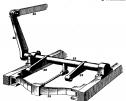 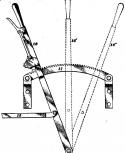 Date: 01/24/12 21:04 Re: counterbalance Author: PorterNo2 Here is a movie we made on Sunday (just goofing around) of the completed valve gear rebuild on Santa Cruz Portland Cement #2 (aka the "Chiggen"). In this video you can see how the johnson bar actuates the tumbling shaft which moves the links. This engine is Stephenson valve gear equipped. As in the wood block print above, this tumbling shaft is spring balanced, using a double coil spring. It is easy to see the weight of the links and blades which are at play on an engine such as this, requiring this balance. If this short clip interests you, go to www.scpc2.com for more information regarding this project.
Best, Stathi __________________ Efstathios I. Pappas, MS Chief Mechanical Officer Mt. Rainier Scenic Railroad You must be a registered subscriber to watch videos. Join Today! Date: 01/25/12 16:55 Re: ICC mandate for power reverse gear Author: Bob3985 Good job Don. This has been a great string of conversation. I, fortunately, only had exerience with the power assisted reverse on the UP locomotives. I did get to very briefly work the 618 at Heber but not enough to gain true experience on it.
Bob Krieger Cheyenne, WY Date: 01/26/12 04:43 Re: ICC mandate for power reverse gear Author: donstrack donstrack Wrote:
------------------------------------------------------- > Yet to be > answered is why UP no. 61 had the device, at > 200,1000 pounds weight on drivers, but UP Shay no. > 59 did not, with its 146,800 pounds weight on > drivers. I have photos of both sides of no. 59 on > its way to be scrapped, and there is no similar > mechanism visible. A simple explanation might be > that no. 59 never received Class 3 repairs after > the power reverse rule was mandated. To answer the question about UP's Shay no. 59 not receiving power reverse gear, two days ago I received a PDF of a drawing from the Union Pacific Historical Society's archive that shows the arrangement intended for no. 59. The drawing is dated August 23, 1941, and shows what the arrangement would have been. A rod-and-lever mechanism from the engineer's side, using both one-inch pipe and 1-1/2-inch solid bar for the rods, across the backhead to the fireman's side, then an arrangement similar to what no. 61 had but inside the cab wall, down to the power reverse gear, which was to be mounted to the outside of the locomotive's I-beam frame just ahead of the cab. The power reverse gear would then operate a heavier 2-1/2-inch rod and lever mechanism mounted under the frame, back to the engineer's side, where it was attached to the cylinders. There is a note on the drawing, "Not Issued Acct Application Not Required." Maybe someday, we will find out why the feature was "not required" on no. 59. Don Strack Date: 01/26/12 07:15 Re: ICC mandate for power reverse gear Author: PorterNo2 And the reason is th 59 was a road engine under 150,000 lbs. I am sure the tintic district was not all in yard limits. There were not too many shays used in captive yard service where the icc distinction would apply. The current Fra rules for steam still distinguish road vs yard locomotive standards for running gear.
Best Stathi Posted from iPhone Date: 01/26/12 14:42 Re: ICC mandate for power reverse gear Author: nycman Stathi, neat video of the Chiggen's reverse gear. Nice to see John and Adam at work, as usual.
|