| Home | Open Account | Help | 374 users online |
|
Member Login
Discussion
Media SharingHostingLibrarySite Info |
Steam & Excursion > Help with RR car brake linkage ratios requestedDate: 12/14/12 14:57 Help with RR car brake linkage ratios requested Author: Kimball I am building some "Live Steam" 2-1/2" Scale, 7-1/2" gaue N. G. flatcars (from various plans) and am up to the brake linkage. I am having trouble working out the correct proportions of the car main lever and car dead lever. None of the plans or diagrams agree.
The two main links that come off the car main lever lever have to be spaced to be between the inside sills and the center sill, so they can reach the trucks, so I know their spacing. The cylinder and chain connection are out by the outer sill, so I know where they have to be. When the chain is wound up, or the cylinder extends, they exert a pull on the end of the car main lever. This is turn exterts a pull on the car main lever, and so the nearest linkage is pulled tight, setting the brakes on the "A" end truck. When that gets tight, the lever will pivot on the "A" linkage, and so then exert a pull on the "B" truck, in the opposite direction, as is needed. However, the "A" end gets too much force! I built a wooden mock-up to play with the proportions, placing soft extension springs to measure the force at each truck by measuring the spring lengths. It seems the function of the car dead lever is to reduce the "A" end force to match the "B" end, but how do I deduce the proper ratio? Date: 12/14/12 17:46 Re: Help with RR car brake linkage ratios requested Author: wcamp1472 Kimball..
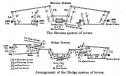
I don't have drawings in front of me, but the 'physics' wants to have the tension of the levers that extend to the A & B ends of the car to be equal. I'm not sure about the 'dead-lever' anchoring. I suspect that the lever is a 'floating lever' and the pivots should be spaced at about the 50% points --- to geometrically divide the tension forces equally to each truck I'll try to locate drawing in my Car Cyclopedias to reference. Let me know about a close prototype you'd like to represent. Wes. Date: 12/14/12 19:38 Re: Help with RR car brake linkage ratios requested Author: EtoinShrdlu This sounds like the Hodge system of levers, which was supplanted by the Stevens system a long time ago. The Hodge system has be prohibited from US railroad cars since at least 1880, or something like that.
Date: 12/18/12 13:36 Re: Help with RR car brake linkage ratios requested Author: mario_puzo See generic diagram for reference layout of both lever systems. Source is "Principles of Locomotive Operation & Train Control", Wood, A.J., McGraw-Hill, 1915 from Google digital library. Book looks like a good technical source on a wide range of RR subjects from the teens.
 |