| Home | Open Account | Help | 258 users online |
|
Member Login
Discussion
Media SharingHostingLibrarySite Info |
Steam & Excursion > Harriman Vanderbilt Tender Vestibules?Date: 11/18/14 10:23 Harriman Vanderbilt Tender Vestibules? Author: hogheaded I recently acquired a couple old, scratchy negatives of a couple of SP steamers with tender vestibules, as they were called - basically buffers for passenger car diaphragms. I'm guessing most of the Harriman Lines had some loco tenders with these devices built circa 1905-10, and have seen pictures some new ones built in the early Twenties for the LA&SL. Pullman apparently came up with the idea, as an anti-telescoping feature, and displayed a compound 4-4-0 with one at the 1893 Columbian Exposition (below). The Gould Coupler Company later came out with a vestibule similar to Pullman's.
I've found plans at Google books for Harriman square tender vestibules, but have never seen a picture of one. Did SP actually construct any? The Vanderbilt tenders with vestibules are pretty cool, and I'd like to model SP's single ex-EP&SW PR-2 2-6-2 Commute engine. Does anyone have a closeup photo of said vestibule? I remember seeing a great one in a book. When did SP remove the last vestibules? I haven't seen any photos of them later than the mid-30's. -E.O. Photo 1: SP 1777, supposedly at the Lenzen Avenuse roundhouse in San Jose c1935. This is the only 2-6-0 that I've encountered with a tender vestibule - as far as I know, only 4-4-2's and 4-6-2's came with them originally. The arrangement of the oil (?) tank and buildings looks wrong for San Jose, however. The 1777 was not vacated until 1958. Photo 2: SP E-3 3046 w/vestibule and E-23 1445 (later renumbered 1502) at West Oakland (at the location of the present diesel shops) presumably in storage (3046 was scrapped in 1936) on 4-14-35. I kinda remember a photo somewhere of an E-23 with a vestibule, as well. Photo 3: The 1893 Columbian Exposition engine. Gould Coupler Company later marketed a very similar vestibule. Edited 3 time(s). Last edit at 11/18/14 10:46 by hogheaded. 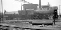 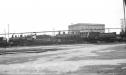 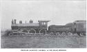 Date: 11/18/14 11:59 Re: Harriman Vanderbilt Tender Vestibules? Author: wingomann Check out the thread below. One of these still exists at the Mount Rainier Scenic Railroad.
http://www.trainorders.com/discussion/read.php?10,3575315,3575494#msg-3575494 Date: 11/18/14 15:20 Re: Harriman Vanderbilt Tender Vestibules? Author: Realist The UP 4-6-0 displayed in the Union Station museum in Omaha has a tender that previously was on a 4-4-2. It has the remains of the mounting of a tender vestibule.
From various books, it appears that the idea was to steady the rear of the tender and the front of the first car at high speeds when the tender water level was low and it was thus lighter, such as before a water stop. Date: 11/18/14 16:03 Re: Harriman Vanderbilt Tender Vestibules? Author: hogheaded wingomann Wrote:
------------------------------------------------------- > Check out the thread below. One of these still > exists at the Mount Rainier Scenic Railroad. > http://www.trainorders.com/discussion/read.php?10, > 3575315,3575494#msg-3575494 Wow! I had no idea that one of these tenders still exists. Looks like a field trip is in order. Thanks! Realist Wrote: ------------------------------------------------------- > From various books, it appears that the idea was > to steady the rear of the tender and the front of > the first car at high speeds when the tender water > level was low and it was thus lighter, such as > before a water stop. This makes a lot of sense, given that there was no such thing as TightLock couplers. A light tender certainly would get buffed around by longer and heavier passenger cars while stopping. Similarly, as I understand it, in a case of a collision, it was thought the tender would ride-up upon the newfangled diaphragm buffer plate and telescope into the head car. A large assortment of anticlimber-type end-sills were patented during the period (later: all-steel cars), and seem to eventually have obviated the need for tender vestibules in the latter respect. -E.O. Date: 11/18/14 18:41 Re: Harriman Vanderbilt Tender Vestibules? Author: PorterNo2 With passenger cars of the ought years, the draft gear was only partially responsible for taking the various compressive forces present. Cars of this era had very substantial buffer mechanisms under the end platforms that were intended to absorb this type of slack action. The design of many of these end buffers was included in the diaphragm plate as a single unit in the center with telescoping springs and sliding followers with additional spring value. This system is not unlike that found on British and European cars, but is a single ram in the middle of the car end incorporated into the apron plate.
By having a complete diaphragm plate on the tender, this allowed the buffer system to function and prevent excessive compression (read slack action) at the joint between the tender and train. Thus, the whole train behaved as a unit, simplifying train handling. Now why would this have been a problem then, and not later? I have never seen this written, but this is my guess that the transition from A1 combined straight air/automatic to 6ET was the cause. As someone with lots of time on both types of air, 6ET allows more effective use of stretch braking as A1 did not always come with a method for bailing off the locomotive and tender. Also the use of F, P, and L triple valves on the cars did not provide accelerated promulgation of the brake pipe reduction like UC, D22 and later valves did. Thus, the longer the train, the greater the time between the front setting up and the rear. This was not an insignificant amount of time with these older airs. All this would exacerbate the additional slack between the tender and train. The coming of 6ET and an easily bailable independent made things far easier for dragging a train to a stop or reducing speed. The fall of the tender buffer mechanism is at the right time for the conversion to 6ET, all the evidence and my personal experiences running trains with many cars of this era with both types of air would support this interpretation. Final point, diaphragm plates of this era were often supported at the four corners with spring loaded bars running into the end of the car. These had hinges or ball and socket joints to allow tilting around the center buffer bar. However they were not able to handle much flexture between top and bottom. Hence the need for the full diaphragm plate to prevent damage to the whole assembly. Best, Stathi Date: 11/19/14 09:41 Re: Harriman Vanderbilt Tender Vestibules? Author: hogheaded PorterNo2 Wrote:
------------------------------------------------------- > With passenger cars of the ought years, the draft > gear was only partially responsible for taking the > various compressive forces present. Cars of this > era had very substantial buffer mechanisms under > the end platforms that were intended to absorb > this type of slack action. The design of many of > these end buffers was included in the diaphragm > plate as a single unit in the center with > telescoping springs and sliding followers with > additional spring value. This system is not > unlike that found on British and European cars, > but is a single ram in the middle of the car end > incorporated into the apron plate. > > By having a complete diaphragm plate on the > tender, this allowed the buffer system to function > and prevent excessive compression (read slack > action) at the joint between the tender and train. > Thus, the whole train behaved as a unit, > simplifying train handling. Now why would this > have been a problem then, and not later? I have > never seen this written, but this is my guess that > the transition from A1 combined straight > air/automatic to 6ET was the cause. As someone > with lots of time on both types of air, 6ET allows > more effective use of stretch braking as A1 did > not always come with a method for bailing off the > locomotive and tender. Also the use of F, P, and > L triple valves on the cars did not provide > accelerated promulgation of the brake pipe > reduction like UC, D22 and later valves did. > Thus, the longer the train, the greater the time > between the front setting up and the rear. This > was not an insignificant amount of time with these > older airs. All this would exacerbate the > additional slack between the tender and train. > > The coming of 6ET and an easily bailable > independent made things far easier for dragging a > train to a stop or reducing speed. The fall of > the tender buffer mechanism is at the right time > for the conversion to 6ET, all the evidence and my > personal experiences running trains with many cars > of this era with both types of air would support > this interpretation. Final point, diaphragm > plates of this era were often supported at the > four corners with spring loaded bars running into > the end of the car. These had hinges or ball and > socket joints to allow tilting around the center > buffer bar. However they were not able to handle > much flexture between top and bottom. Hence the > need for the full diaphragm plate to prevent > damage to the whole assembly. > > Best, > > Stathi I only have experience with 6-ET and later, so please bear with my ignorance with earlier arrangements. First, I'm not sure that I have heard of the A1 straight/auto air. I'm only familiar with the term's modern use as the A-1 Charging/Cut-Off Pilot Valve. How did the A1 function in relation to auto/straight air? As far as braking trains under any system, I would assume that either the engine could be bailed, or otherwise the automatic would only have set-up the train, yes? How else would an engineer brake the train at high speed, or for an extended period without overheating and losing his tires? In general, your explanation helps me see why buff would have been a big problem, given the seeming wide variation in promulgation rates in early equipment. With a long passenger train of mixed systems, the engineer would have had to have a pretty good yank going to keep slower-setting cars from running into the quicker setting ones. This must have been a bugger when making initial sets at low speeds. As far as the tender vestibules go, maybe the simple answer might be that they really did not make that much of a difference, practically speaking. Their limited use may speak to that. To me, this is fascinating stuff and bears more investigation. Thanks for the post! -E.O. Here's a page from Google: 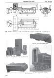 Date: 11/22/14 17:02 Re: Harriman Vanderbilt Tender Vestibules? Author: EtoinShrdlu To correct a few urban legends which have crept in from all over the place:
> Now why would this have been a problem then, and not later? I have never seen this written, but this is my guess that the transition from A1 combined straight air/automatic to 6ET was the cause. A-1 is/was automatic air only. SWA is the combined automatic and straight air system (on the locomotive). Somewhere along the line, the two have become conflated. To repeat: A-1 did/does not have straight air. >As someone with lots of time on both types of air, 6ET allows more effective use of stretch braking as A1 did not always come with a method for bailing off the locomotive and tender. True, because A-1 is automatic-only on the engine. However, if the company bought SWA and the straight air release attachment for the straight air valve (making it an S-3-A straight air valve) and installed the necessary check valve and piping for its use, then you could "bail" an automatic set on the locomotive. >Also the use of F, P, and L triple valves on the cars did not provide accelerated promulgation of the brake pipe reduction like UC, D22 and later valves did. F-46, H, and P triples did not have quick service. L and all later triple/control valves do (and never mind the traction triple valves). > Thus, the longer the train, the greater the time between the front setting up and the rear. This is true except when the initial set by the engineer is 6 psi and all the triple/control valves have quick service. >This was not an insignificant amount of time with these older airs. A 30-CDW brake valve exhausts the brake pipe at the same rate a G-6 does, as do all other automatic brake valves do, especially those equipped with equalizing pistons. >All this would exacerbate the additional slack between the tender and train Slack problems arise primarily with the initial set, which is what quick service was designed to counter (and it does a good job of it, provided you use it). If you measure the time it takes for the brake pipe of a 50 car train of F-46 and H triples to reduce to 50 psi using a G-6 valve, it would be the same as for a 50 car train of AB using a 30-CDW valve, provided the AB train has no cars equipped with reduction relay valves or AB valves with the continuous quick service feature (ABD-W and ABX/ABDXL). Date: 11/24/14 09:56 Re: Harriman Vanderbilt Tender Vestibules? Author: PorterNo2 Good points, perhaps I should flesh out my argument a bit more:
> > A-1 is/was automatic air only. SWA is the combined > automatic and straight air system (on the > locomotive). Somewhere along the line, the two > have become conflated. To repeat: A-1 did/does not > have straight air. Perhaps I should have said a1/combined straight air automatic, but I am aware of the difference. In the interest of simplicity I omitted this distinction. > > True, because A-1 is automatic-only on the engine. > However, if the company bought SWA and the > straight air release attachment for the straight > air valve (making it an S-3-A straight air valve) > and installed the necessary check valve and piping > for its use, then you could "bail" an automatic > set on the locomotive. Combined straight air automatic does not come with a bail feature. It can be equipped with a whistle valve or foot operated valve that bleeds the air out of the brake cylinders giving the effect of a bail, but it is not a true bail in any sense of the word. Most engines never had this feature installed, and all it did was "piss away" your air on the locomotive. You basically only had 3 or 4 of these releases before you had no more air to set up the locomotive with an automatic application. This is a very different animal than 6ET where the air for the locomotive brakes comes from the main reservoir and is "pressure maintained" as long as main res pressure is above that required by the locomotive brake cylinders either using independent or automatic. Some locomotives were also equipped with driver brake cut outs but this again was not standard practice. Also, the Westinghouse literature also specified that one could not use both straight air and automatic at the same time. If a stop was being made with straight air, automatic was not be be used and vice versa as the double check valves could stick and prevent the total release of the engine brake without making a full set of each brake separately to assure a total release. This would be mostly impossible without stopping. Again, this is a very different animal from 6ET and later airs and requires a great deal of judgement to prevent problems. > > F-46, H, and P triples did not have quick service. > L and all later triple/control valves do (and > never mind the traction triple valves). > > > Thus, the longer the train, the greater the time > between the front setting up and the rear. > > This is true except when the initial set by the > engineer is 6 psi and all the triple/control > valves have quick service. > >This was not an insignificant amount of time with > these older airs. > > A 30-CDW brake valve exhausts the brake pipe at > the same rate a G-6 does, as do all other > automatic brake valves do, especially those > equipped with equalizing pistons. > As I said, cars without quick service (I used layman's terms so as to help those less versed in air to understand) can greatly lengthen the propagation of the set. > >All this would exacerbate the additional slack > between the tender and train > > Slack problems arise primarily with the initial > set, which is what quick service was designed to > counter (and it does a good job of it, provided > you use it). > > If you measure the time it takes for the brake > pipe of a 50 car train of F-46 and H triples to > reduce to 50 psi using a G-6 valve, it would be > the same as for a 50 car train of AB using a > 30-CDW valve, provided the AB train has no cars > equipped with reduction relay valves or AB valves > with the continuous quick service feature (ABD-W > and ABX/ABDXL). This is true, but the problem is the engine in these older locomotive air brake schedules would set up much faster than the cars causing bunching at the non buffered joint between tender and train. Also remember, in this era, brake pipes could be made out of 1" pipe, or 1 1/4" pipe. This provided bottle necking of the reduction if the train was so equipped, thus slowing down the set further. This was supposed to be standardized for passenger and freight cars but in the early 20th century there still was a great deal of variability. In sum, most locomotives with A1/combined straight air automatic did not have a way to "bail off" the engine and tender which taken with non-quick service triples led to slack action at the joint between engine and train. Once again, the locomotive airs were not up to the task for much longer trains and higher speeds. Best, Stathi Date: 11/24/14 18:45 Re: Harriman Vanderbilt Tender Vestibules? Author: EtoinShrdlu >Combined straight air automatic does not come with a bail feature.
It did if you bought it that way. This is the difference between S-3 and S-3-A straight air valves. An S-3-A is an S-3 with a [WABCo made] add-on, specifically designed to bail the engine brakes. >It can be equipped with a whistle valve or foot operated valve that bleeds the air out of the brake cylinders giving the effect of a bail, but it is not a true bail in any sense of the word. I've seen and used this type of add-on valve. If you want to be really specific about the meaning of "bailing", the only independent brake valve that I know of which actually uses a real live bail arrangement for this purpose is the S-40, found in in 24-RL. >You basically only had 3 or 4 of these releases before you had no more air to set up the locomotive with an automatic application. The same is true for the brakes on the train. >This is a very different animal than 6ET where the air for the locomotive brakes comes from the main reservoir and is "pressure maintained" as long as main res pressure is above that required by the locomotive brake cylinders either using independent or automatic. Some locomotives were also equipped with driver brake cut outs but this again was not standard practice. Well, with SWA the air for the BCs also comes from the main reservoir. The #6 distributing valve's ability to maintain BC pressure against leakage is a function of how leak free the the components making up the application cylinder pipe apparatus are. >Also, the Westinghouse literature also specified that one could not use both straight air and automatic at the same time. Never seen this in the literature . . just looked in instruction book 5027 of 5-1931, and it specifically says you can. >If a stop was being made with straight air, automatic was not be be used and vice versa as the double check valves could stick and prevent the total release of the engine brake without making a full set of each brake separately to assure a total release. Sticking check valve? Or the check valve shutting off the BC source which is the lowest in pressure? >As I said, cars without quick service (I used layman's terms so as to help those less versed in air to understand) can greatly lengthen the propagation of the set. You said something like "older airs took longer to apply". This is not the case because every air brake system put on the market since the F-46 operates just the same with respect to applications (except of course for quick service, which the F-46, H, and P don't have). The MCB/ARA/AAR have specified backwards compatibility in this respect this since about 1890. With quick service the timing is quite different, but only when quick service is operating. >This is true, but the problem is the engine in these older locomotive air brake schedules would set up much faster than the cars causing bunching at the non buffered joint between tender and train. I can tell you here and now that this is true for modern locomotives too. F-59s with 26-L will set up much faster than the cars behind them, including passenger cars with 26-C. I know of several Amtrak engineers who routinely got a lot slack action with 4 car passenger trains because of this. >Also remember, in this era, brake pipes could be made out of 1" pipe, or 1 1/4" pipe. This provided bottle necking of the reduction if the train was so equipped, thus slowing down the set further. After the latter part of the 1890s, the 1 1/4" brake pipe became a standard. Retrofitting the rest of the hundreds of thousands of freight and passenger cars was a completely different thing, although accelerated by the phase-out of wood-frame freight cars in the first two decades of the 1900s. > . . . most locomotives with A1/combined straight air automatic did not have a way to "bail off" the engine and tender which taken with non-quick service triples led to slack action at the joint between engine and train. As I said earlier, this run-in is still true today. It has more to do with the braking ratios of the equipment, loco vs empty or loaded freight car, than air flow in the brake pipe. >Once again, the locomotive airs were not up to the task for much longer trains and higher speeds. Longer train problems were related to the brake systems on the cars; higher speed issues were related to the braking power of the cars in the train, specifically the brake cylinder pressures and leverage ratios of them. Date: 11/24/14 18:53 Re: Harriman Vanderbilt Tender Vestibules? Author: EtoinShrdlu Went back through the thread (that pic at WO caught my eye, having worked there for a long time), and it seems to me that the tender vestibules had more to do with keeping dust and dirt out of the leading car's front vestibule (and therefore the car itself) than anything else, particularly on a coal burning road with all the cinders and soot coming from the locomotive.
Date: 11/25/14 11:48 Re: Harriman Vanderbilt Tender Vestibules? Author: Realist Don't you guys watch old movies? It made it much easier for train
robbers to get from the train to the cab. Date: 11/29/14 01:19 Re: Harriman Vanderbilt Tender Vestibules? Author: lwilton Stop thinking about brake rigging and pressures and propagation, and start thinking about the train as a string of cars. What are the physical characteristics of the cars? How do they behave in tension and compression?
As best I recall, wooden passenger cars had a pretty stiff and rigid floor and undercarriage, not unlike a flatcar. There was, I believe, a set of load-carrying members under the center of the floor, ending in the buffer blocks at each end, that left about 4" gap between the coupled cars. In compression (when stopping) the central buffer posts or plugs on each end of each car pressed against the other one, coupling the stopping force cleanly from one end of the train to the other, assuming all cars had buffer blocks. The only ones I can think of that might not have had compatible buffer blocks would have been the caboose and the engine/tender pair. Now, if the base of the passenger car is a flatcar, what about the rest of it? It was, I believe, a fairly stiff and thick-walled box, well attached to the floor. This box was, as best I can tell, quite stiff. I can't recall ever seeing any pictures where in an accident a passenger car "tilted" -- the individual side wall strips came lose from each other and the whole car just laid down flat. I do recall seeing lots of pictures of passenger cars tossed about like matchsticks, probably killing everyone inside, but with no appreciable damage to any of the cars themselves. If the car is rigid longitudinally, then when a buff force appears on the front buffer block, the car will not compress in length much, and that same force will appear on the rear buffer block. But since the car is a rigid box with very little flexture, the top of the rear door frame is going to retain it's spatial relationship to the rear buffer block. In effect the car can transmit braking force not only thru the buffer blocks, but also through the spring space fillers between the ends of the cars. As a practical matter, this force is applied to the end of the car, the end of the car behaves as a stiff sheet and transfers the force to the wooden corner posts. From there it will be effectively transferred diagonally downward into the sill, and from there to the core structural members of the car. Looking at the forces from that point of view suggests an "impedance bump" (to use some radio engineering terminology) between the front car and the rear of the tender. The buffer beams would match up in compression, if the tender had one of the right size and shape. And this will carry the buff forces, as long as they stay lined up. But there is no back force on the front of the front car, and there is a forward force (from the trailing train) on the rear of the front car. This moment is going to tend to rotate the front of the front car downward, and the back of the tender upward. If the tender is light, it could ride over the buffer beam of the front car and go for a jaunt down the center of the car. If you put a tender vestibule on the tender (and note it is made of steel, and the front surface is sloped) then you engage the remainder of the car-coupling surface on the front car. The front car no longer has an off-axis couple pushing down on the front end, and the tender rear is not inclined to ride up, since it will start trying to lift the front end of the front car before it rides very far. This also puts less stress on the front car during a stop, since the forces are balanced, as they are for all other cars except possibly the last one. Overall it is a fairly simple gizmo that a) prevents tender telescoping; b) reducers stresses on the lead car; c) makes it harder for robbers to get to the engine to make their exit; keeps the people in the front car clean if someone leaves the front door open. Seems like a good idea to me, unless you instead eliminate the buff force between the first car and the tender, and when stopping, effectively have the leading car of the train pull the tender and engine to a stop. Of course, to do that you can't apply engine brakes. Edited 2 time(s). Last edit at 11/29/14 01:25 by lwilton. |