| Home | Open Account | Help | 292 users online |
|
Member Login
Discussion
Media SharingHostingLibrarySite Info |
Steam & Excursion > Bad 4-8-4s ? & "Dynamic Augment" question..Date: 02/25/17 05:33 Bad 4-8-4s ? & "Dynamic Augment" question.. Author: wcamp1472 The term Dynamic Augment was used to describe the effects of off-center counterweights, whirling drivers and centrifugal forces at work during track speed operations.
Early, low-power steamers did not use counterweights on their drivers, or they were very small. As locos got bigger, and larger pistons were used, the engine frames were pounded --mostly at the end of the piston stroke, where the pistons reversed direction. Counterweights on the drivers were applied to mitigate the strains on the drive rods, the crosshead s and the reciprocating machinery---- at the ends of the piston strokes.... Whirling counterweights always apply lopsided, unbalanced forces to the whirling structure, from the center out.... regardless of the horizontal center lines, it produces 360 degrees of imbalance The greater the speed of rotation, the greater the off-center force ( is the hammer throw the Olympic sport where humans swing a large weight in a circle, and toss it for the greatest distance?). Thus, the force is dependent on the size of the mass, and the speed of rotation. In whirling drivers, the force is exerted in 360 degrees of rotation, not just at the ends of the piston stroke..... Early counterbalancing-thought simply weighed the reciprocating parts, applied the same weights, divided among the axles, and balanced the static weight of the reciprocating components.... At track speed, the whirling counterweights exerted great off-center forces..... the weights, across the top arc of the wheel, lifted the axles & wheels off the rails!!!!! At the bottom of the whirl-arc, the counterweights and the spring weights on the axles KINKED the rails at regular intervals. I've seen pictures of a PRR test track in South Jersey, that shows kinked rails from such destructive effects*. So counterbalancing developed into the ART of compromise. Constantly changing driver/track speeds complicate the math, the higher the rotational speed the greater the centrifugal forces ------ increases as the square of the rotational speeds. So, mostly through experimentation was the only way to solve the problem. In fact, the drivers have hollow counterweight cavities, that are later weighted with molten lead, which may not fill the entire cast voids. Towards the end of steam, engineers found the smaller weights, at the other end of the axle could off-set some of the mass of the primary counterweights. That led to the addition of smaller weights, on the opposite driver's, -----at ends of the 'primary' counterweight. You can often see wedge shaped blocks in between the spokes. The final variant was including all the weighting, including the cross-counterbalancing into one, integrated counterweight. Typically, the integrated, offset counterweights were part of the design of the vendor-provided, cast drivers, with hollow spokes, etc. The single countweight in this scheme, is actually offset from the crank centerline by a few degrees, and the ends are not symmetrically opposite to the crank. Its a very subtle shift, but if ( strike a tangent line) you divide the ends of the semicircular weight, that centerline would be offset from the centerline of the crank, through the axle. Thus, a seemingly 'tilted' counterweight. Probably there are no greater puzzles in the deign of reciprocating machines than the solutions needed for compromise counterewighting of the necessary offsets in the crank 'systems'.... The 'red-line' on your automobile's engine, is the point at which the crankshaft counterweights take command and destroy your engine... W. *IIRC, E. P. Alexander's book on the PRR, has pics of the kinked rails, by massive over-counterweighting ..... Edited 5 time(s). Last edit at 02/25/17 07:42 by wcamp1472. Date: 02/25/17 05:46 Re: Bad 4-8-4s ? & "Dynamic Augment" question.. Author: gbmott Wes
Very good explanation of dynamic augment, but I believe you are thinking of the Hammer Throw. Curling is played indoors on what looks like a large ice-covered bowling lane where a stone is slid from one end and people with brooms walk ahead of it, sweeping to guide the stone to a desired location. Gordon Date: 02/25/17 06:04 Re: Bad 4-8-4s ? & "Dynamic Augment" question.. Author: wcamp1472 Thanks, I'll make the correction.....I also thought about a sport using a weight on a rope, maybe.
The principle's the same... W. Edited 1 time(s). Last edit at 02/25/17 06:55 by wcamp1472. Date: 02/25/17 08:20 Re: Bad 4-8-4s ? & "Dynamic Augment" question.. Author: CofSF As a youngster, when Grandpa and I visited the 3751 at the park in San Berdoo, he casually mentioned that he hated the 3700's that came through his territory (he was once an AT&SF section foreman at Prado Dam [on the transcon just east of Orange County, CA], claiming he had to follow them out of town lifting all the kinks in his track. On the other hand, he specifically mentioned that he loved the 2900s. Loved the discussion, BTW ... Thanks!
-bill Date: 02/25/17 08:46 Re: Bad 4-8-4s ? & "Dynamic Augment" question.. Author: TrackGuy Wes, great explanation of the physics going on with the reciprocating drive system in a steam locomotive.
This is the principle reason why a certain ore-hauling ten-coupled engine could not be operated over about 35 mph without imparting excessive stress on the railroads track and bridge structure and why she's never really been welcomed on any existing shortline. Question: is there any feasible way to improve the counterbalancing characteristics in a steam locomotive today with technology that wasnt available back in the 30s and 40s, particularly to improve a locomotive that does not have the benefit of light weight rods and roller bearings on the crankpins? TrackGuy Posted from Android Date: 02/25/17 08:48 Re: Bad 4-8-4s ? & "Dynamic Augment" question.. Author: callum_out I've said it before, I'll say it again, Wes, I'm amazed at your depth of knowledge but moreover what you bring
in terms of mainline steam issues. Us museum rebuilders don't get the 60 mph stuff, we worry more about rod brasses than dynamic augmentation! Out Date: 02/25/17 10:05 Re: Bad 4-8-4s ? & "Dynamic Augment" question.. Author: wcamp1472 Question: is there any feasible way to improve the
> counterbalancing characteristics in a steam > locomotive today with technology that wasnt > available back in the 30s and 40s, particularly to > improve a locomotive that does not have the > benefit of light weight rods and roller bearings > on the crankpins? ACTUALLY, rollerbearings on the rods increases the msss of the reciprocating parts.... Timken's design, on 4-8-4s, uses separate, two-ended rods for the siderods, proper. The main rod uses a barrel-shaped pressed-in wrist pin at the crosshead, with cage-less rollers on each side. The other siderods each contain the rollers, brass bushings, end retainer plates, etc The typical application, on a 4-8-4, uses two 'tandem' rods from driver two to driver three, the outer error is a tender rod, sandwiched at the front end is the Big End of the main rod ( at the front, and the connecting rod to driver four ( on the thirds axle). Conecting rod from driver two, forward to driver no. 1 is next to the wheels hubs. So, starting at number one driver, it is fitted with a complete roller aeesmbly at the front end, its rear has a roller assembly at the no. 2 axle, next to the hub. No. 2 crankpin carries 4 rod assemblies: the back end of siderods rod to no. 1 axle, the front end of the inner 'tandem rod, the back end of the main rod, the front end of tandem rod no. 2. Crankpin no.3 carries the rear on the inner tandem rod, the front of the rear driver siderods, the rear bearing assembly of outer tandem rod. Driver 4 contains the bearing assembly at that rod's back-end. The main advantage of this complex assembly was the need 'free-play" at each connection rod ( provided by the brass and the roller cage). The free-play is a very small amount of 'rattle" ---- the roller assembly is very precise, but requires some looseness. [.those of you that have re-packed front wheels bearings on older cars ( not front-wheel dricpves) rember the the procedure.....tighten the nut until firm and snug, than back-off the nut 'ONE FLAT' before applying the lock--- to establish the proper "Pre-load"] With roller applications, there is SO MUCH more in the way of reciprocating masses, the Timken reduced the weight of siderod mass by employing stronger steels than conventional siderods are fabricated from. The next mass-reducing steps were in the use of forged, hollow piston rods , lighter piston castings and lighter crossheads. The roller bearing application, to the rods, presented an other problem: the rods severly limit the axle 'end-wise' shift necessary to get 4 axles through track curves and vertical irregularities...... by using the individual, 2-ended siderods, each rod end has that little bit of 'pre-load' for wiggle-room -----,the side rods must shift a little as they navigate curves. Each roller assembly accommodates a little bit of lateral shift. During the shift, the distance between the adjacent crankpin must necessarily INCREASE, the rods need to stretch, a little. Not so easy as with sloppy plain bearings. So, while axle rollers are an absolute necessity, over plain bearings, roller rod bearings, not so much. BACK to the original question about counterweights and better calculations. it is my belief that computer algorithms can be more easily employed to do the intricate, tedious calculations necessary for precise counterweight proportions. You can also run very accurate RPM simulations, and relanly predict the forces at all operational speeds. Plain bearing siderods are inherently lighter than the roller equipped locos, and I'd bet that there are modern improvements in the bearing components that make better, lighter bearing elements. Graphite-impregnated materials come to mind.... So YES, intodays world, there are so many advantages to use. That's why I'm still excited by the progress of the project to build a PRR T-1, from the ground-up. We need everybody's cash support to move ahead more rapidly, and we need this community's support for introductions to the vast ( speculation) money resources that are lolling around in low-interest bearing accounts. Read the book about Six Degrees of Separation for inspiration. There are so many technologies and learning opportunities out there.... let's get this thing rolling. Contact me or Brad Noble with your ideas... Would we use a complete Roller Bearing application, side rods and all? Absolutely, we've only got two connected drive axles per 'engine'--- very easy, and cheap to do.... We are tantalizingly close to success, we need your ideas and solutions - improved technology is our secret, innovation is our inspiration! W. Edited 2 time(s). Last edit at 02/25/17 10:22 by wcamp1472. Date: 02/25/17 10:07 Re: Bad 4-8-4s ? & "Dynamic Augment" question.. Author: drumwrencher Thanks, Wes. Excellent explaination, as usual. I'll pretend it wasn't waay past my level! :) One small thing: "Redline" is the point where an engine stops making horsepower, torque, or rpm's, depending on what one is measuring. "Over Revving" is where pieces start to fly... Walter
Edited 2 time(s). Last edit at 02/25/17 10:24 by drumwrencher. 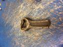 Date: 02/25/17 10:26 Re: Bad 4-8-4s ? & "Dynamic Augment" question.. Author: wcamp1472 I've heard of "over-revving" jet engines, too....
Tell me about that poor conn rod? W. Date: 02/25/17 11:15 Re: Bad 4-8-4s ? & "Dynamic Augment" question.. Author: drumwrencher Matching piston. I keep them on my workbench. Years ago, on my last race team, we had a kid driver they called "Stretch"... he wound it up tight, and missed second. It actually still ran - if you've ever had the head off a 4 cylinder, you know TDC has two pistons up, and two down. This one had three up...
I never tried to get the wrist pin out. I suppose it'll pry out, but then there's nothing to talk about. Walter Oh, dirt track racer. Small cars, big 4 cylinders. 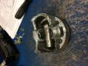 Date: 02/25/17 12:08 Re: Bad 4-8-4s ? & "Dynamic Augment" question.. Author: spnudge I had a piston and what was left of the rod. It was off an SD-9 that let go on helper one night on the Siskiyous. It was a Sunday so all the power had to go to Dunsmuir for their weekly. I wrote the engine up and you could see oil and green water on the gangway. I got my rest and was called for the Weed Local Tuesday morning. I had the same SD-9. I went back into the office and told the operator the engine was B/O. About that time the RFE walked in and said, "Just take it". Well, I did.
I went back out, and started her up. After 30 seconds you could hear the banging and pounding from the engine. It was loud enough to bring everyone out of the office. I looked at the RFE and shrugged my shoulders. He starting yelling, shut it down, shut it down. I did. There was a bent rod and a piece of the piston laying on the gangway on the fireman's side along with other oil covered pieces. The sump was full of parts. Why the RH said the power was okay to run, i never heard. I threw the two pieces in the back of my truck and had a buddy run them through a dip tank. If you look at them you can see how much force it must have taken to twist the rod. I used to listen to the old heads when they talked about steam engines, and "breaking" something at speed. Art Langlois told me about hitting about 70 on a commute going west just past Santa Clara Tower. He was the fireman. He said all of a sudden, the engine started bucking, like it broke a rod. Each revolution the engine would leap up in the air on his side and crash back down. All of a sudden, things started to calm down and off to the left was a tire off a driver, rolling along, out into a field and they were still on the rails. He said the tire broke and that would usually derail an engine at speed. For some reason when it came down on one of the revolutions the broken gap went by all the rods and main at the same time and just kept rolling. I guess the worst would be breaking a rod and having it come back up and wipe part of the cab away along with some personal. Nudge Date: 02/26/17 07:51 Re: Bad 4-8-4s ? & "Dynamic Augment" question.. Author: junctiontower Just a thought about reciprocating engines red lines. While the theory of setting the redline ata point the engine can no longer produce more power by increasing RPM is probably fine for a full on race engine, most street engines and budget race engines would be better served by having their redline set as a safety factor for the weakest part in the engine. I have built several budget minded 350 Chevy engines that had camshafts, heads and intake manifolds capable of producing horsepower north of of 6000 RPM, but cast cranks, stock connecting rods, cast pistons and unguided stock pushrods limit their safe RPM to something lower. I limit the interim engine I currently have in my Chevelle to 5500 RPM on upshifts, and 4500 sustained RPM, even though at 5500 the engine is still accelerating like a runaway freight train.
Date: 02/26/17 21:40 Re: Bad 4-8-4s ? & "Dynamic Augment" question.. Author: drumwrencher Wow. I'd love to have seen that SD-9 - still running, banging away! You said you "had" pieces - does that mean you no longer do? Love to see a pic...
Thanks, Nudge Walter PS My dad used to tell the story of the 4355 breaking a mainpin eastbound out of Redwood City back in the twenties - they towed her to Bayshore, but I don't believe she came apart at speed. I'm betting Art and crew thanked their stars they made it thru THAT trip OK... Edited 1 time(s). Last edit at 02/26/17 21:45 by drumwrencher. Date: 02/27/17 16:47 Re: Bad 4-8-4s ? & "Dynamic Augment" question.. Author: SteveC spnudge Wrote:
------------------------------------------------------- > > > I guess the worst would be breaking a rod and > having it come back up and wipe part of the cab > away along with some personal. > > > Nudge That was one of the real dangers with camelback locomotives. The engineer was sitting right above the rod. If it broke, it would tear through the bottom of the cab. I remember seeing a photo of a cab that was badly torn up from a rod failure. Steve Date: 02/27/17 18:08 Re: Bad 4-8-4s ? & "Dynamic Augment" question.. Author: SR-RL_Nr_10 SteveC Wrote:
> > That was one of the real dangers with camelback > locomotives. The engineer was sitting right > above the rod. If it broke, it would tear > through the bottom of the cab. I remember seeing > a photo of a cab that was badly torn up from a rod > failure. > > Steve Sort of like this: 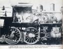 Date: 02/27/17 19:14 Re: Bad 4-8-4s ? & "Dynamic Augment" question.. Author: SteveC Wow! That is a scary photo!
Yikes! Date: 02/28/17 05:52 Re: Bad 4-8-4s ? & "Dynamic Augment" question.. Author: jtbrandt Would love to see that kinked rail photo. I have that PRR pictorial book, and that photo isn't in it, at least in my edition.
Date: 02/28/17 07:39 Re: Bad 4-8-4s ? & "Dynamic Augment" question.. Author: sgriggs jtbrandt Wrote:
------------------------------------------------------- > Would love to see that kinked rail photo. I have > that PRR pictorial book, and that photo isn't in > it, at least in my edition. From 'The Steam Locomotive' by Ralph P. Johnson: 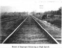 Date: 02/28/17 08:39 Re: Bad 4-8-4s ? & "Dynamic Augment" question.. Author: jtbrandt HOLY MOLY!!
Thanks! sgriggs Wrote: ------------------------------------------------------- > jtbrandt Wrote: > -------------------------------------------------- > ----- > > Would love to see that kinked rail photo. I > have > > that PRR pictorial book, and that photo isn't > in > > it, at least in my edition. > > From 'The Steam Locomotive' by Ralph P. Johnson: > > Date: 02/28/17 17:24 Re: Bad 4-8-4s ? & "Dynamic Augment" question.. Author: wcamp1472 I think it was Fred Westing that described PRR's south Jersey test track for measuring Dynamic Augment in the early 1900s
They equipped a long stretch of track with 'test tie plates', these were steel plates had hardened steel balls, like pin-ball machines used, set under rails and on steel test plates. The plates were sequentially numbered for later laboratory analysis. They would run locos over these sections, and replace the test plates after each run. In the labs, they would measure the indentation pattern and make a chart of the test run specifics. The highest deformation of the plates was at the bottom of the crank arc, and wheel-lift at the top of the crank-arc would leave no discernible marks. Both rails would be equipped with test plates. Successful counterbalancing was an imperfect science in those days, so they backwards-engineered the counterbalancing as the tests showed improvements in less-severely dented plates. It was mostly by trial and error, searching for the best compromise. And that's the challenge, the counterweighting was always a search for acceptable compromises.... Driver RPMs varied, and so the centrifugal forces varied widely. Maybe in today's world we could come up with suitable algorithms, for the counterweight mass, the 'best ' driver diameter, I also think that they could used the Altoona Works loco test plant for getting closer to developing mathematical approximations for counterbalancing. But I doubt that they would have risked the test plant apparatus to unknown stresses, so my presumption is that in the plant, they tested proven designs that could be examined for tweaking, rather than just spinning and see what happened..... Thanks for the picture of the dented rails, above. Wes Edited 2 time(s). Last edit at 03/02/17 14:49 by wcamp1472. |