| Home | Open Account | Help | 361 users online |
|
Member Login
Discussion
Media SharingHostingLibrarySite Info |
Steam & Excursion > AAR Power Control PanelDate: 05/21/17 06:17 AAR Power Control Panel Author: Southern3205 I figure this was a good a spot as any to ask this. I've acquired a throttle/power control panel for an EMD locomotive and have begun the reassembly process. I was wondering if someone out there might know, have a description of, or schematics/drawings showing how this thing was connecting to the (electrical) control system. Any help is much appreciated. I've attached pictures of the before and what it looks like now. I still have to separate the wiring and wipe it all down to clean it up, then I'll be getting hold of new clamps to secure everything. Since I work in aviation, I was able to secure a 28 volt bulb for the "notch indicator" and bypass the voltage dropping resistor so as to be able to tie all of the lighting onto a common power bus.
Opinions? For some reason I can't get the pics to load vertically so as to appear as they were taken. Edited 1 time(s). Last edit at 05/21/17 06:18 by Southern3205. 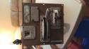 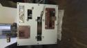 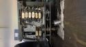 Date: 05/21/17 06:23 Re: AAR Power Control Panel Author: HotWater Well, not "Steam & Excursion" related, but that is the AAR Controller Mechanism out of an EMD control stand. Pretty rough, too.
Date: 05/21/17 06:38 Re: AAR Power Control Panel Author: Southern3205 I figured since it's also an "excursion" and thus possibly "preservation" minded this would be a suitable place to post. It was in pretty bad shape when received but has since been sandblasted/stripped, primed and painted. The aluminum housing on the back has only been clear coated to show the diferences in materials.
Date: 05/21/17 07:52 Re: AAR Power Control Panel Author: jointauthority Whats the point in wiring it, are you installing this in a locomotive, are you turning it into a model train controller, are you using it in a train simulator, or do you just want the lights to light up?
Posted from Android Date: 05/21/17 08:20 Re: AAR Power Control Panel Author: Southern3205 In response to joint authority,
I plan to eventually install it in a stand, then connect it to an audio controller that will ramp up/down along with the control settings. What I'm curious about, is what kind of junction point/block/bar was used to connect everything? As far as what was actually on the locomotive, I figured there was probably some sort of cam system on a throttle shaft (on the prime mover) that would correspond with the cams on the controller. Correct me if I'm wrong. Date: 05/21/17 08:32 Re: AAR Power Control Panel Author: HotWater Southern3205 Wrote:
------------------------------------------------------- > In response to joint authority, > > I plan to eventually install it in a stand, then > connect it to an audio controller that will ramp > up/down along with the control settings. What I'm > curious about, is what kind of junction > point/block/bar was used to connect everything? > As far as what was actually on the locomotive, I > figured there was probably some sort of cam system > on a throttle shaft (on the prime mover) that > would correspond with the cams on the controller. > Correct me if I'm wrong. OK, to correct you, the throttle control of prime mover engine speeds was/is all accomplished electrically. That Controller Mechanism you have was screwed into an much larger steel control stand, which had many other electrical components inside, including terminal boards for all the wire connections. The various throttle steps were thus transmitted, electrically, to the Throttle Response Panel (in the main high voltage electrical cabinet) as well as the various load control modules, which then sent the necessary electrical commands to the Electro-Hydraulic Governor, mounted on the frontend of the prime mover. The Woodward PG Governor then controlled the injector layshaft for the desired engine speed step requested by the Engineer in the cab. Date: 05/21/17 08:38 Re: AAR Power Control Panel Author: wcamp1472 GOOD JOB, JACK ....
WELL PUT, CONCISE AND UNDERSTANDABLE... Don t want to confuse them at this early stage.. Thanks for the K.I.S.S. explanation. Wes. Date: 05/21/17 09:12 Re: AAR Power Control Panel Author: Southern3205 To Hotwater,
Thanks for the explanation of the control process. While I was aware of the mounting of the in cab controls, I just didn't know how the control inputs were actually transmitted and applied (I'm used to working on aircraft, not locomotives, so this is all a learning curve). I'll have to see if I can find some pictures of the controller on the prime mover now. That sounds like an interesting set up that may work similar to some fly by wire systems now. Date: 05/21/17 09:23 Re: AAR Power Control Panel Author: PHall Southern 3205, the Governor (think Jet Engine Fuel Control) on the engine has four solenoids that control the engine speed.
The output from the throttle handle controls those solenoids on the governor. Date: 05/21/17 09:40 Re: AAR Power Control Panel Author: Southern3205 To PHall,
Thank you sir. I've started looking at the governors and have found some pictures of the internals. With being controlled by solenoids, I'm assuming the solenoids are connected to some sort of shuttle valves blocking/opening various ports to accomplish the different positions needed for the output to the lay shaft (?). Date: 05/21/17 09:42 Re: AAR Power Control Panel Author: HotWater The more I look at that Controller Mechanism, the more I realize that it probably is NOT the "AAR Design", from say a Dash-2 unit. It appears to be the older style Controller Mechanism, with the selector control lever "window" blanked over, thus there would be no dynamic brake. The "AAR Design" Controller Mechanism would have a separate lever for dynamic brake (if so equipped) and a throttle/power lever, but NO "selector lever" window.
Date: 05/21/17 09:43 Re: AAR Power Control Panel Author: HotWater Southern3205 Wrote:
------------------------------------------------------- > To PHall, > > Thank you sir. I've started looking at the > governors and have found some pictures of the > internals. With being controlled by solenoids, > I'm assuming the solenoids are connected to some > sort of shuttle valves blocking/opening various > ports to accomplish the different positions needed > for the output to the lay shaft (?). No, not really. You probably need to look deeper into a Woodward PG governor design and operation. Date: 05/21/17 10:26 Re: AAR Power Control Panel Author: Southern3205 To Hotwater,
Roger that, I'm in the beginning stages of all of this so definitely appreciate the help with all of this. Are there any particular manuals or other info sources I should look up to find how all this works? I'll respond back here as soon as I can, I'm overseas on contract and have a 0300 wake up call, so it's now time to call it a night. Date: 05/21/17 12:10 Re: AAR Power Control Panel Author: wcamp1472 I had good luck locating the manual for Woodward manual...
Search on Google for: "Woodward Product Manual 36694" Concentrate on the PG-series. Basic concept: spinning fly-weights ( a heavy circular ring) are spring-biased in a near vertical position. As the input shaft spins, the weight-ring tries to assume a near-horizontal position, against the influence of the bias spring. The weight ring raises through delicate levers & regulates a hydraulic-controlling fluid-control pilot- valve....the object being to maintain equilibrium between shaft input RPMs and fuel control the the prime mover. Equilibrium means the spring fly-weights stay away from their relaxed position, in a near vertical position. They are spinning in a more horizontal plane. The ring control spring and mechanism keeps trying to reduce power, but the governor increases fuel, thus increasing engine RPMs. The balancing principlle, restores the selected, but increased, RPMs. Upon receiving input commands from the throttle controls, sugnalling a desire for increased RPMs, the hydraulic control valve increase the fuel to prime mover... As the engine RPMs increase, the fly-ring tilts to return the hydraulic control valve to equilibrium....only now equilibrium his achieved at a very precise increase in shaft input RPMs. Thus the prime mover is putting more power into the main generator.... So, what you're looking for, is the balancing act as each throttle request is responded to, by the balanced, spinning fly-weight governor. HOWVER, the 'Load' on the Main Generator , the trailing train, tends to try to stall the diesel RPMs, thus there are electrical controls regulating the allowable 'Load' from the train, into the Main Geneartor. The Woodward Governors sense the increased load, by the bogging-down of the crankshaft RPMs, and increase the fuel to restore the intended Engine Speed. Remember, that as the crankshaft slows down, the flyweights slow down and fuel is tncreased to get the fly-weights spinning faster At some point, the maximum fuel feed to the engine, is reached and then the governor tends to reduce the Electrica/ Main Generator' excitation magnetic field, to the lower the MG field density, the less load is on the crankshaft , and engine RPMs are restored...although at a lower power-output. It is a main feature of the Woodward Governors to regulate both the engine RPMs and the allowable' load' , for the selected RPM for the engine's crank. So, to haul heavy trains multiple prime movers must be employed to keep the upper engine-RPM/ within the capacity of the engines' power output capacity. As you try to read the manual, you will uncover the 4-solenoids that increase the pressure on the governor's flyweight controlling mechanism.---increased pressure equals need for increased crankshaft RPMs. The solenoids are simply electro-magnets that have only two ( stable) positions energized and de-energized. In the Woodward use the 'energized ' position pushes the plunger to its lowest position, upon de-energizing, a return spring restores the plunger to its relaxed, upper, position. The plungers act on a triangular swash plate, who's center pivot pushes down on the fly-ring shaft, with increased throttle positions from the control stand. Your exam question is: "Who invented the system of Fly-weights used for prime mover RPMs-control, why and about when did he employ this scheme ?" Extra credit for detail about the original use of this mechanical device. Wes C. Edited 4 time(s). Last edit at 05/21/17 20:36 by wcamp1472. Date: 05/21/17 18:23 Re: AAR Power Control Panel Author: EtoinShrdlu >"Who invented the system of Fly-weights used for prime mover RPMs-control, why and about when did he employ this scheme ?"
Flyball governors go back to 19th Century stationary steam engines, like Corliss, Joy, Fitchburg, and so forth. Date: 05/21/17 19:40 Re: AAR Power Control Panel Author: Margaret_SP_fan > Extra credit for detail about the original use of this mechanical device.
Waterwheels. Well - IF that is what you are asking about. My only info about this comes from a Google search, which led me to this Wikipedia article: https://en.wikipedia.org/wiki/Woodward,_Inc. Thank very much for the fascinating details about bow diesel-electric locomotives work! Southern3205 -- Thanks for starting this interesting thread. Fascinating.....I wish you good luck in getting that controller mechanism fixed up. Edited 1 time(s). Last edit at 05/21/17 19:58 by Margaret_SP_fan. Date: 05/21/17 20:10 Re: AAR Power Control Panel Author: wcamp1472 In my early studies about early steam engine developers, it was James Watt that first used the "flyball " engine governor.
He was marketing his engines to power English fabric-making mills in which the mills' machines were powered by steam engine driven line-shafts. The load on the factory engine was constantly varying, as looms, etc. were taken off the line and brought back on line, thus RPMs varied widely ---so Watt used that system first...After perfecting his work on steam, Watt The went into electrical observations, including quantifying the energy termed in "Watts", he also correleated watts to Horse Power... 747 watts equals 1 HP. 1HP is the amount of work required to lift 33,000 lbs, 1 foot in 1 minute ( to be verified).... He used HP as a sales tool for selling engines to mills, replacing water powered operations. Wes On European gasoline powered engines are rated in Watts, not in HP.....Watts are derived from engine dynamometers....they "load" the engines in a test bed, that has the engine's crankshaft driving an electrical generator, connected to a ' load bank' of resistors, precision calibrated for accurate power measurements.. In America, HP is often wildly exaggerated in order to sell more motor cars...1,000 hp V-8!racing engines ....yeah, I'll bet they aren't putting-out that amount of true HP..... THEN THERES, " Crowbar HorsePower"..... Edited 3 time(s). Last edit at 05/21/17 20:49 by wcamp1472. Date: 05/21/17 20:52 Re: AAR Power Control Panel Author: Southern3205 To all,
Many thanks for all of the responses and information, as well as encouragement, I didn't realize it would turn into the valued information source it now is. Now that I have an idea of how the controller is suppose to work and interface with the rest of the system, I can work on developing schematics for what I'm wanting to do. I'll post back when I finally get it all together. Now to figure out the plumbing for that brake controller.......... Date: 05/21/17 21:07 Re: AAR Power Control Panel Author: wcamp1472 WHATTT????
"Now to figure out the plumbing for that brake > controller.........."????? You won't find any plumbing on the 'Dynamic Brake' controller..... it involves solely controlling electrical resistance braking to retard trains on long down grades... It does not control the plumbing of the train's pneumatic Air Brakes, and the related compressors, storage systems and control valves... It's an entirely separate retardation scheme.... See also: Dynamic Braking and Regenerative Braking..... W. Date: 05/22/17 04:42 Re: AAR Power Control Panel Author: donstrack if you can take a close-up photo of the ID plate on your controller, I can tell you from the part number what type of locomotive it came from.
...or, tell us all what the numbers stamped on the ID plate are. Don Strack |