| Home | Open Account | Help | 306 users online |
|
Member Login
Discussion
Media SharingHostingLibrarySite Info |
Steam & Excursion > NKP 765 in Black and White (Part Two)Date: 04/02/24 21:50 NKP 765 in Black and White (Part Two) Author: refarkas (Part Two) When I first started taking photos over fifty years ago, my dad had a darkroom in the basement of our house. I learned to develop and print black and white negatives. I also fell in love with the beauty of black and white. I found a set of color images I had posted on Trainorders over the years and thought I'd take a shot at turning those images into black and white.
Here are two more views of NKP 765 processed into black and white. They are from September 9, 2010. Both are from unknown Ohio locations on the W&LE when NKP 765 was making its eastbound ferry move to the Cuyahoga Valley Scenic Railroad's "Steam in the Valley 2010". 3) Yes, this is from the same time when the crew of NKP 765 made the smoke in photo two. Photos two and three were the only time I caught so much black smoke. 4) Here is NKP 765 at another unknown location west of Medina, Ohio. Bob 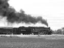 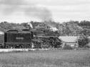 Date: 04/03/24 02:12 Re: NKP 765 in Black and White (Part Two) Author: wcamp1472 A beautiful and well cared-for NKP steamer.
Built during WW2, she, and members of her class, was allowed to have Timken roller bearings for her pilot truck and driver axles, the rest were plain bearings. About a decade ago, 765 was up-graded to roller bearings on all axles.... a worthy improvement. Plain bearings on engine trucks have poor lateral load-bearing capabilities --- plain-bearing pilot trucks have poor-performing qualties, whle trying to negotiate track curves. Rollers as crucial to pilot trucks because they can convert the lateral forces ( curves, switches, etc.) to rolling pressures applied to the truck frames. Roller bearings surround the entire axle; and thus, can do a better job of leading through the curves... The truck frames are hung from 4 sets of double-pin suspension links. The double pins are at the top of the suspension links. The use of two pivots at the top of tye links, means that as the axles move towards either side, the swing links try to lift the front of tye engine --- but, in actuality, the front of the loco creeps over as the rotating tires slightly move across the rail-head. The increased pressures on the wheel-sets are applied by the more tightly compressed springs bearing on the tops of the axle journal boxes. When on level, tangent rails, the links are nearly vertical; however, in curves the truck moves to the side, and the 4 links pivot on one of their two suspension pins at the top of each link. As the curve gets tighter, the links tend to lift the front of the engine --- but, lifting all that weight actually forces the front of the axle & frame to move towards the 'high' links, restoring lhe links to their 'low' position, while steering the engine through the curves in the tracks. So, in long curves the pilot truck's links are pulling the loco closer to the imaginary center of the curve... and back to tangent track the suspension links relax to their lower, centered, position. Similar inverted rockers apply the same centering forces at the rear, outer corners of the truck frames. There are two, curved, pivot rockers that apply lifting forces --- that actually nudge the rear of the frames to bring the loco frames over, as the rolling wheels to coax the rear weight of the loco to bring the loco over towards the centered, 'low', resting state. The curved ramps of the rear rockers. have their "center pivots" as the opposite pin at the rockers' base: the center pivot of the right-ramp is the left pin, at the base. As the truck frame moves left or right, the curved ramps apply more pressure onto the trailer-truck springs, riding on the axles & their journal boxes. The centering mechanisms remove the lateral, grinding forces away from excessively wearing the driver flanges. The driver tires are relieved from having to do the double duty of both providing the locos' tractive power, and having to guide the locos through the rails' curvy tracks. Without guiding trucks the flanges on axles 1 and 4 get prematurely worn, and thinner. The remedy for thin flanges is to cut the tread down and reduce the tire thickness, while getting the flanges back to original thickness. Producing a BIG problem... However, you now have created a 'big problem' because driver axles' 1 & 4 are now smaller in circumference, than axles 2 & 3. That disparity causes excessive pressures and increased wear to all the crankpin bearings. The cure is that ALL the driver tires on the loco must be machined & cut to the same dimension in a wheel lathe, and all must be cut to the same as the driver-diameter with the thinnest flanges. So, worn flanges are a challenge when you have a whole fleet of engines all needing 'wheel' work. Guiding mechanisms of the pilot and trailing trucks, move the loco frame into the curves, and reduce tire wear at axles 1 & 4 !! Generally, when flanges get worn, loco back-shops can lift the loco, and apply a spare set 4 drivers, all with the same circumference. Thus, reducing down-time of the loco, instead of waiting for all the drivers in set #1 to be cut. They simply applied fresh sets of restored wheel sets. While, allowing drivers of set #1 to casually visit the wheel lathe for new profiles. Then, the "renewed-profile-set" #1 gets added to 'stock' , ready for the next engine that needs 'new' tires. That's one reason NKP stuck with their 80 copies of the same basic engine... Typically, new tires get applied when an axle-set has had 4 trips to the wheel lathe. Such worn tires were routinely scrapped, and new tires were shrunk onto the cast wheel centers.* Loco tires are made from really TOUGH, high quality steels. Many worn-out & cut-off driver tires were used by local communities to become alarm 'bells' for emergency fire and ambulance companies. Ask, the local fire department if you can give their loco tire a hard SMACK, to see how loud a bell the tire can RING!. You'd be astounded at how far away you can hear a ringing loco tire when it's given a hard smack. But, it helps, if there's one cut to the tire rim! Try it, you'll have fun...but get permission first! OR, if you have a true energency, ring it repeatedly... and your local volunteer responders will come-running, from miles away !!! W. ( * Like, when buying a horse from a previous owner, check the horse's teeth before agreeing on a price... When evaluating loco candidates to consider for restoration, pick the ones with the new-like tires. Railroads, back in the day, only applied new tire sets, when an engine had completed major boiler inspections, got fresh tubes and complete firebox-work, and all the running mechanisms have been replaced with new or qualified components). Edited 6 time(s). Last edit at 04/03/24 11:14 by wcamp1472. Date: 04/03/24 06:21 Re: NKP 765 in Black and White (Part Two) Author: refarkas Thank you, wcamp1472. You gave so much information to help us better understand the running and the maintenance of a steam locomotive.
Bob Date: 04/03/24 10:44 Re: NKP 765 in Black and White (Part Two) Author: ClubCar I like the photos; however, as I have stated before, nothing can beat a outstanding color photograph in my opinion. Thanks Bob, for sharing your fine photos, and thank you Wes for your explanations and stories from the steam world.
John in White Marsh, Maryland Date: 04/03/24 19:54 Re: NKP 765 in Black and White (Part Two) Author: weather Likewise, great info as always Wes. MHY question, how much more effecient is a roller bearing engine vs. no roller bearing one of the same class.844 vs. 4449. I realized that the horseopowercurve might be the same by I would think the TE might be higher. Your thoughts?
Date: 04/04/24 00:33 Re: NKP 765 in Black and White (Part Two) Author: wcamp1472 In my experience, there is no perceivable difference between the
two types of driver bearings. The superior aspects of rollers have more to do with more effective load distribution of the axial-loading forces. That refers specifically to the way end-wise movements, side-to side thrusts, which are better controlled by the roller bearings. On plain bearings, end-wise free-play is limited by the inner hubs of the drivers. When plain bearings are rolling down the tracks the axle hubs do not continually rub against the semi-circular, brass "hub liners" part of the journal brass. The axle journal carries the weight of a driver's main springs. The vertical face of a plain bearing's journal box has a crescent-shaped, flat brass running surface that is the 'bearing surface' that the faces the wheels' flat, inner.hub: that brass ( semi-circular) surface of the journal box is called the hub-liner. The plain, brass bearings only carry the weight on the top half of the axle. Hub-liners and the driver's wheel hubs contact each other ONLY when the loco frame goes around track curves. It's difficult to adequately lubricate the wheel hubs. Many schemes were developed to try to provide adequate oil-flow when the wheel hubs are rubbing against the hub-liners of the journal boxes. The best schemes involved pumped oil specifically to the hub surfaces. One of the best solutions was used by the SP locos which were equipped with oil feeds from a mechanical lubricator. Other methods were tried, but most were intermittent in solving the hub-wear problems. Timken's unique solution uses tapered rollers surrounding the axles at the journal boxes. Timken's tapered rollers ride on matching, cone-shaped inner ( rotating) races, and the larger, tapered outer races. But, the roller bearings only support end-wise thrusts when the axle tries move the rotating inner race against and through the fixed, outer race. When the axle moves AWAY from the outer race, the rollers lose contact and are useless. So, Timken roller bearings are used in pairs, back-to-back, so endwise thrusts are controlled by either one of the sets of tapered rollers. There must be free, loose, rolling-space of several thousandths of an inch to allow the rollers to have free space. You will find 2 similar, facing, Timken roller bearings at the front wheels of motor vehicles. They're used in pairs, back-to-back. The use of two sets of tapered rollers, back-to-back, provides 360-degrees of bearing support when navigating track curves. The end-wise free-play is limited to a few thousands of an inch, vs. up-to 3/4" of end play allowed by plain bearings. Back in the day, when I used to read temperture graphs of plain bearing, 'hot box' detectors, I was astounded by the higher temperature readings of the roller bearing journal boxes, vs the lower temperature spikes of the plain bearing equipped freight cars! All the temperature spikes of the roller-equipped cars were uniformly running at temperatures above 100 F. Plain bearing cars' axle temperatures were just a little bit above ambient outdoor temperatures. The hotter temperature readings of the roller bearings tells me that there is greater rolling friction in roller-equipped cars, compared to the plain bearings. That's because the plain bearings ride on a completely oil-covered rolling axle. When rotating, the journals' surfaces are 100% riding on a fluid film of oil, there is NO metal-to-metal contact between the fixed journal bearing and the axle's rolling surface. It's totally covered with journal oil. So, it's a myth that rollers run cooler than plain bearings. However, because of the much slower rotating speeds of steam locos' driver axles, means that axle's rollers run at the same temperatures as the surrounding weather conditions. What makes Timken's solution work so well, is that their tapered races and rollers make much better bearings for end-wise axle thrusts. The only time they raise problems is when the lubricant runs-out. W. Proofing, still.... Edited 2 time(s). Last edit at 04/04/24 00:50 by wcamp1472. |