| Home | Open Account | Help | 171 users online |
|
Member Login
Discussion
Media SharingHostingLibrarySite Info |
Model Railroading > 21 pin decoder connectionsDate: 11/20/14 19:19 21 pin decoder connections Author: fbe My apology, I promised I would not start any more 21 pin threads but here is some of the information I have harvested in my quest to know the 21 pin interface. I think enough of you will have interest to find this useful.
I think a way to connect each of the pins will be useful especially if the modeler wants to bring DCC to older locomotives. ESU, the Lok Sound people make a way to do this. Think of this as a blank motherboard. This is a beginning of a hardwire install. All light outputs are 16 volt so appropriate resistors need to be added to the necessary connections. The part number is 51967. Here is the pin diagram for the 21 pin plug from the Open DCC link which funnelfan sent to me. Most of the connections are self explanatory. You can use pin 16+ and pin 20- for keep alive hardware. Pins 1, 2, 3 are for the device used to synch steam chuffs using wheel mounted magnets. Maybe this can be used for axle cams. Please enjoy and save the files. 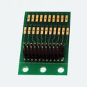 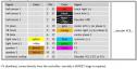 Date: 11/20/14 21:40 Re: 21 pin decoder connections Author: rschonfelder Alan, this is good and I did not have this so will keep. I am, however, a bit confused. The graphic shows 22 pin descriptions but the image is of a 21 pin harness.
Rick Edited 1 time(s). Last edit at 11/20/14 21:42 by rschonfelder. Date: 11/20/14 22:03 Re: 21 pin decoder connections Author: fbe That is account the pin #11 is an index point. There is no actual pin on the male side and the hole in the female side is plugged making it impossible to reverse the connection. That leaves 21 actual connections available. I am not sure why the adapter card has a solder point for pin 11. If you have an 8 function decoder you will have to leave two wires off the decoder if that is an option and then wire them out in the air somewhere. The next generation of connectors has even more pins to allow for this.
Edited 1 time(s). Last edit at 11/20/14 22:49 by fbe. Date: 11/21/14 08:09 Re: 21 pin decoder connections Author: shadetree I think if I were converting one I'd take a sharpie and blacken out #11 to keep me from soldering to it.
Eng.Shadetree Posted from Android Date: 11/21/14 12:00 Re: 21 pin decoder connections Author: fbe The #11 pad might be used to connect a resistor or something.
Posted from Windows Phone OS 7 Date: 11/22/14 20:14 Re: 21 pin decoder connections Author: fbe Rick,
I see what you mean here, there is no pin connection with number 22 like the diagram shows. According to my local dealer two of these are on the way for me. When they get here next week I will get out the multi meter and check continuity for what is really there. Date: 11/25/14 13:02 Re: 21 pin decoder connections Author: fbe I think there are two different numbering conventions used here. The paper counts pins of which there are 22 in the design spec. One of them, the #11 pin is not used and in fact is blocked to keep the decoder connection properly oriented.
The actual part as manufactured counts the true number of connections which can be physically completed. There are 10 possible connections on pins 1-10 and no physical pin where #11 would be. On the far row of pins there are 11 pins with 11 possible connections. Since the last connection on the front row was 10 the numbers on the far row start at 11. I guess we can remember to add one number to the second row of numbers when soldering or paint a white stripe over numbers 11-21 and use a fine marker to change them to 12-22 to match the printed diagram. Posted from Windows Phone OS 7 Date: 11/26/14 19:16 Re: 21 pin decoder connections on the 9-21 pin harness Author: fbe Now we have the basics down let's go to the 9 pin to 21 pin harness. We can work out the 9 decoder wires will connect to pins 7-8-14-15-16-18-19-21-22. But wait! On the bottom of the 21 pin socket I find 3 solder pads which connect to pins 4-13-20. What does that do for us? Pin 4 is AUX4,pin 13 is AUX3 and pin 20. The AUX gives another pair(?) of light outputs. Pin 20 is a ground wire. This is useful since you can attach the + wire from a keep alive circuit to the lighting common on the mother board and the - keep alive wire to this solder pad.
This is good. I note there is no explanation of this in the harness or TCS 1358 packaging. Posted from Windows Phone OS 7 Date: 12/02/14 16:37 Re: 21 pin decoder connections Author: fbe I now have the 21 pin solder connector in hand to really check one out. Pin 11 has no connection so it is not numbered. Pin 12 thus has connection number 11 which is stenciled on to the circuit board. So either remember 1 to each connection number greater than 10 or paint or decal a stripe over the stenciled connection numbers and use a fine sharpie to renumber them to the pin numbers.
There are matching solder pads on both sides of the card. It might be convenient to solder the 1-10 pin connections on one side of the board and the 12-22 pin connections on the other side. The decoder sits over the solder pad end of the connector board after the solder joints are made so this is very compact. The three mounting holes can be broken off on the scribed line. All the instructions are in German though use is pretty intuitive, thank goodness. I will think about picking a heritage unit and adding a 21 pin decoder to it using this connector to install it. I have a couple of Stewart Century Alcos with SP light packages which might be interesting to work with. That means a lot of resistors to wire in somehow. Maybe Loc Sound would be nice. No wonder I have so many unfinished projects in the back shop. Posted from Windows Phone OS 7 |