| Home | Open Account | Help | 215 users online |
|
Member Login
Discussion
Media SharingHostingLibrarySite Info |
Model Railroading > ST SD40T-2 – Inside the Beast – Phase 6 - “Conduit”Date: 06/02/19 23:49 ST SD40T-2 – Inside the Beast – Phase 6 - “Conduit” Author: tmotor (This is Phase 6 of this project. The earlier 5 Phases were posted in previous weeks.)
In the lower right corner of the front wall, two conduits enter to provide power for the fans. They run horizontal along the floor, and then make a 90 for a vertical run to meet a fan motor. When viewing the prototype trackside, the vertical conduit is easily mistaken for the silhouette of a handrail stanchion, which is why for many years I had no idea the conduit run existed. Since I didn’t even know they were there, should the conduit be modeled, or not? Since I’m a Licensed Electrical Contractor, you can probably guess I chose to model the conduit runs. Even though it will complicate the install, somehow I just couldn’t leave out the conduit. After all of conduit I have bent and installed in my day, if there is a chance for me to install conduit on my own T-Motor, it’s going to happen! The conduit size appears to be approximately the diameter of a handrail. The railroad environment is too harsh for the EMT (Electro Mechanical Tube) thin-wall conduit found on a residential install, so let’s go with 1” rigid conduit. (This is essentially water pipe, and has much thicker walls than EMT. Very durable, but takes a gorilla to bend with a manual conduit bender. Most likely EMD used hydraulic equipment to bend it.) The OD (Outside Diameter) is about 1.25”. Phosphor-bronze wire 0.020” in diameter (or something reasonably close) will work. Measuring the distance from the front wall to the centers of the fans gives 0.43” and 1.27”. Measure-over that far (minimum) on a piece of Phosphor-bronze wire, and begin the bend. There will be a bend at the bottom, and another in the opposite direction at the top, forming a Z-shape. A jig is the best way to ensure consistent results. 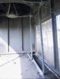 Date: 06/02/19 23:52 Re: ST SD40T-2 – Inside the Beast – Phase 6 - “Conduit” Author: tmotor The bends produced by a 0.125” (1/8”) brass rod as a mandrel looked about right. Round-over the edges of the end of the 1/8” rod, and cut a ½” piece off. Repeat, so there are now 2 pins. A scrap of bamboo flooring was cut in half length-wise. Holes were drilled near the edge and the pins glued into the holes. The 2 halves will slide against each other to adjust the distance between the 2 pins. Clamping them in-place will fix the distance and it is ready for a test-bend.
The front and rear walls extend vertically 0.495”. This is the maximum height for the conduit assembly, so the pins were set that far apart. The initial bends proved to be a bit too tall. Though the jig pins were (theoretically) at the correct spacing (being the height of the walls), the “spring-back” of the wire added height to the finished part. No matter how tightly the wire was held against the pins during the bends, it could not compensate for the spring-back. The distance between the pins was moved closer together and re-clamped. Another piece of wire was bent, and the height measured. The distance between the pins was fine-tuned, until the part produced was at the correct height. A line was drawn across both halves of the jig to indicate the spacing that produced the proper part, so after unclamping the jig, repeating the part in the future will be easy. 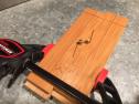 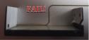 Date: 06/02/19 23:54 Re: ST SD40T-2 – Inside the Beast – Phase 6 - “Conduit” Author: tmotor The pair of conduits (Yellow lines) start at the forward wall, run along the floor. The conduit closest to the diamond plate then makes a 90 and goes vertical, while the other conduit continues along the floor for a bit more before also making a 90. At the end of each conduit is a (Junction Box) J-Box (Purple rectangle) that has a socket to accept the pigtail (Green line) that comes from the fan motor housing. The J-Box centers are separated by a distance of 0.383”. Since the Z-shape of each conduit run is identical, the distance between the vertical runs is also 0.383”.
Use the inside of an aluminum channel as a jig to hold the parts upright for soldering. Scribe lines into the vertical wall 0.383” apart to locate the vertical sections of the conduit runs. Position the longer conduit against the vertical wall, with the vertical conduit run lined-up with the right-most scribe line. Apply low temperature solder paste to the horizontal run of the shorter conduit. Position it next to the longer conduit. Ensure both are lined-up with the scribe lines. Use a soldering iron to apply heat to a small area. Let it cool to arrest the movement of the conduit pieces. (The aluminum jig will wick-away heat, so it will take more heat than normal to melt the solder.) Apply heat to different spots where the conduits touch, until all the solder is melted and shines. Applying too much heat will melt all of the solder and the conduits will move independently of each other, rotating out of alignment. Moving the soldering iron tip to various spots to apply heat allows the areas with cooled solder to hold the conduit in alignment. Edited 1 time(s). Last edit at 06/03/19 00:45 by tmotor. 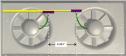 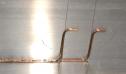 Date: 06/02/19 23:57 Re: ST SD40T-2 – Inside the Beast – Phase 6 - “Conduit” Author: tmotor The floor has diamond plate installed, but it doesn’t cover the entire floor. It does run to the base of each wall, but along the grill-work there is a margin that leaves the floor “exposed”. This margin is approximately 1/6th the width of the floor. (The ribs on the front wall divide the wall into 3rds. The edge of the margin is half of that 1/3rd distance.) Scribe a line from wall to wall, that is 1/6th the width of the floor. This represents the edge of the diamond plate. The pair of conduits run along the floor in the margin area. The longer conduit is in the margin, and the shorter conduit runs on top of the diamond plate. (When diamond plate will be installed, a notch will be cut into it to fit around the conduit run.)
Apply low temperature solder paste to the horizontal run of the conduit assembly. Position the conduit assembly on the Floor Cover, straddling the scribe line. Bring the center of the J-box for the 1st fan so it is 0.635” from the end of the Floor Cover. Place a weight onto the soldered section of the conduit assembly, to arrest its movement. Apply spot-heat to the unsoldered area for the longer conduit. Let the solder cool. Remove the weight. Apply spot-heat to the rest of the conduit assembly. Trim the upper ends of the conduit, leaving a short, straight section for the J-box to attach. Use a 0.040” x 0.040” Evergreen Strip for the body of the J-box. Drill a 0.019” hole into the end of the strip to accept the conduit wire. Round-over 2 adjacent corners to form the side that faces the grill-work. Cut 0.15” off of the end of the strip, which will be the J-box. Repeat the process for the 2nd J-box. Apply thin CA to the end of the conduit. Slide the J-box onto the end of the conduit, with the flat side facing the fan motor. This is the first time I have soldered to tin-plated steel (the Floor Cover) and to my great relief it worked well. The use of low temperature solder allowed a minimum of heat to be used to complete the solder joint. This produced a strong mechanical attachment, and did NOT warp the Floor Cover. During soldering the Floor Cover was placed on the aluminum soldering jig to wick-away heat, which also reduced the chances of warping. The solder joint is a bit “lumpy”, but is mechanically strong. Unless the T-Motor is brand new, there will be an accumulation of debris along the base of the conduit (as can be seen in the prototype photo), so some weathering will camouflage the gaps in the solder joint. CA glue would have worked, and LokTite 430 (metal-to-metal CA) was going to be Plan B if the soldering approach failed. However, I am confident the solder joint will withstand any (reasonable) abuse during removal of the Floor Cover. Certainly the conduits will be severely deformed before the solder joint will fail. Edited 2 time(s). Last edit at 06/03/19 02:12 by tmotor.  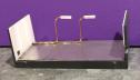 Date: 06/03/19 13:24 Re: ST SD40T-2 – Inside the Beast – Phase 6 - “Conduit” Author: ChrisCampi Looking good!
Date: 06/03/19 13:52 Re: ST SD40T-2 – Inside the Beast – Phase 6 - “Conduit” Author: atsf121 Amazing work! Your reasoning brought a smile to my face. I like the logic. Won’t apply for my line of work, but glad to see you go for it.
Nathan Posted from iPhone Date: 06/04/19 08:27 Re: ST SD40T-2 – Inside the Beast – Phase 6 - “Conduit” Author: tmotor ChrisCampi Wrote:
------------------------------------------------------- > Looking good! Thank you for the kind words. :-D Properly installed conduit is a work of art. There is no "back space key", so once it is bent, other than a few degrees of fine-tuning, it is pretty much right or scrap. And being consistent with full size conduit, I made my share of scrap on this install too. LOL! However, once the jig pins are at the correct distance, creating matching parts is easy. Definitely worth the results. Dave Date: 06/04/19 08:40 Re: ST SD40T-2 – Inside the Beast – Phase 6 - “Conduit” Author: tmotor atsf121 Wrote:
------------------------------------------------------- > Amazing work! Your reasoning brought a smile to > my face. I like the logic. Won’t apply for my > line of work, but glad to see you go for it. > > Nathan I appreciate the positive feedback. ;-) Glad you enjoyed the back-story of why I decided to model an "internal" part that will be rarely noticed. The Scale Trains folks did such a TERRIFIC job that I feel it is worthy of the effort to push it over the top. In order to make the interior details more viewable, I am thinking about removing the grillwork and submerging them in etching solution. This will (theoretically) remove more of the metal, and thin the profile, and make them more "see thru". Of course, this is Risky Business since there are no spare parts available. But that is the subject for another thread... Dave |