| Home | Open Account | Help | 239 users online |
|
Member Login
Discussion
Media SharingHostingLibrarySite Info |
Model Railroading > 3D Printer (Part 13) – More Angle to the DangleDate: 02/13/20 00:28 3D Printer (Part 13) – More Angle to the Dangle Author: tmotor This is Part 13 of a series on my recent experience with an Anycubic “Photon S” 3D printer. (Parts 1 thru 12 were posted earlier.)
When looking at videos covering the process to print parts with resin 3D printers, I noticed all of the parts were printed at an angle. It seemed odd to take a part and angle it to be printed. Why not just keep the part “flat” against the FEP? It would take less time to print, and need less Supports. However, angles are your friend, and here’s why… Think about the new layer of resin on the FEP. As the Build Plate rises, it must yank that new layer off of the FEP. If the part is a hollow rectangle (like a box car) then the floor will be a huge rectangle-shaped layer. That is a significant amount of resistance, and will stress the first layer of resin stuck to the Build Plate. The floor will require many layers, each one tugging on that first layer. If the floor layers print successfully, then the roof layers will, again, create a huge rectangle to tug against the Build Plate. If the part pulls away from the Build Plate, hours of print time will be wasted. To reduce the tug-of-war between the FEP and Build Plate, the part is angled, which significantly reduces the surface area of the layers for the floor and roof. Instead of a solid rectangle-shape, the layers will be hollow rectangles. The part will take a bit longer to print (due to the angle making it “taller”), but it is worth the reduced risk of a part failure. Before adding Supports, raise one end of the part to create an angle of 30 to 45 degrees. Adjust as necessary to stay within the boundary of the Build Volume. After raising one end of the part, tilt it (using the length as the axis of rotation) to 30 to 45 degrees. This keeps the leading edge from being a single line. Why is this important? Remember that each area of the part needs to “grow” from a Support. If the part is not tilted, the very first layer of the leading edge will be a long, thin line. It is not strong enough to be pulled from the FEP, and (at a minimum) will cause the leading edge to be deformed and look like a scalloped edge. Tilting the part places one corner of the part lower than the other. Attaching a Support at that lower corner allows the edges to be supported as new layers are added. To illustrate this, one of the test parts that comes with the printer is a cube matrix. It prints without any Supports. How is that possible? Because the cube was angled to 45 degrees, and then tilted to 45 degrees, so one corner is used to grow the part from the circular base. As the part builds, the new layers are fully attached to previous layers, so no Supports are needed. Though few of the parts for model railroading will look like this, the point is that even a part with very thin components can be successfully printed by angling and tilting the part. The test print of the NSC well car had one end raised and the entire body twisted in the Slicer software, prior to Supports being added. The shortest Support possible is about 8mm, so the part needs to be raised up off of the grid by at least that height in order to place a Support at the lower corner. Edited 4 time(s). Last edit at 02/13/20 08:06 by tmotor. 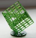 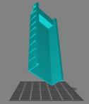 Date: 02/13/20 07:21 Re: 3D Printer (Part 13) – More Angle to the Dangle Author: RRTom So these items are made from the top of the image down, is that correct?
Date: 02/13/20 08:36 Re: 3D Printer (Part 13) – More Angle to the Dangle Author: tmotor RRTom Wrote:
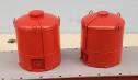
------------------------------------------------------- > So these items are made from the top of the image > down, is that correct? It depends on the frame of reference. As it is viewed on the screen of the Slicer software, the part builds from the bottom up. Consider the Cube, where the large disk is at the bottom of the part. The Cube will look "right-side-up" in the Slicer software, with the large disk at the bottom. From this perspective, the part will build from the bottom up. However, during the printing process, the part is built upside-down. Here is what that Cube looks after it has printed and is still attached to the Build Plate. The large disk is attached to the Build Plate, because it prints the part upside-down. The layers attach to the Build Plate, one by one, until the part is complete. The part is being build from the large disk first, then the entire Cube. Because the part is now upside-down, it is build from the top down. it can be disorienting. It took me a while to wrap my head around the concept, but once I watched a few videos that showed a time lapse of a part being printed, it clicked. But it can produce a bit of vertigo to make the mental gyrations to be flipping the part around in one's head. That is why I just try to reference the image of the part in the Slicer software (which is right-side-up), and trust the printer will understand what I want it to do. Edited 6 time(s). Last edit at 02/13/20 09:14 by tmotor. 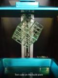 Date: 02/13/20 18:52 Re: 3D Printer (Part 13) – More Angle to the Dangle Author: sixaxlecentury Since I went to the Mars, I have stopped doing angle's on all but very certain things. Once you dial in your supports (which I have now started to do right in the CAD of the part) and exposure settings, I have not had a need to. These are printed right on the plate.
 |