| Home | Open Account | Help | 263 users online |
|
Member Login
Discussion
Media SharingHostingLibrarySite Info |
Model Railroading > 3D Printer (Part 15) – On the Ragged EdgeDate: 02/18/20 11:16 3D Printer (Part 15) – On the Ragged Edge Author: tmotor This is Part 15 of a series on my recent experience with an Anycubic “Photon S” 3D printer. (Parts 1 thru 14 were posted earlier.)
Trying to Scrape By The layer (horizontal) lines were significantly reduced by keeping the temperature constant, but some other lines came to my attention. These lines were vertical lines, instead of horizontal (relative to the FEP). They were consistent across the entire surface of the vertical walls. As an experiment, I carefully scraped one entire side, and gave it a coat of primer. The results were satisfactory, but the process was not sustainable. It took the better part of an hour to scrape just one side, and that was only ¼ of the entire well car. The articulated version has 3 wells. I plan to build a minimum at least 4 sets. The math doesn’t work. Also, one slip with the scraper and the part would be gouged. Moreover, not all areas could be adequately scraped due to tight access. The deal breaker for the scraping solution was the thought of the side of a UPS trailer with tons of rivets. Could it be scraped flat? Yes. Would I do it if that were the only option? Yes. But it seems like such a low-tech solution to a high-tech problem. (Sanding a coat of primer is another option, but has similar issues of time, access to tight areas, and damage to existing details.) There were still more parameters to adjust, so let the games begin. The resin chart indicates the number of seconds per layer for my resin (Siraya Tech BLU) is recommended to be 12 seconds. The default of 8 seconds was originally used, so that was cranked-up to 12. It increased the print time from 4 hours to over 5, but if it removed the lines, I didn’t care. Unfortunately, the vertical lines persisted. Ragged Edge The part was being printed with the one end raised, but without any rotation (along the axis). This kept the vertical walls at a right angle to the FEP and LCD screen. The LCD screen creates a mask to block the UV light, so only the wanted area of resin hardens into the new layer. My theory is that the LCD screen has some variation in the arrangement of the crystals (LCD = Liquid Crystal Display) that is not visible to the naked eye. When the LCD is asked to create a perfectly straight line, the edge is not perfectly straight, but is a bit ragged (at a microscopic level). If the wall of the part is at a right angle to the LCD screen, then the exact same area of the LCD screen will be used to create the mask over and over again, for each layer over the entire wall surface. Any variation in the mask line created by the LCD screen will be repeated over and over, all the way up the wall. The variations of the mask’s edge stack, and vertical lines appear. What is needed is to break-up the pattern generated by the LCD mask. Rotating the part along its axis in the Slicer software will be the next step. 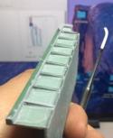 Date: 02/18/20 12:23 Re: 3D Printer (Part 15) – On the Ragged Edge Author: Arved Could diffraction be the culprit? Turbulance of the resin caused by movement of the model as it's moved from one layer to the next?
Arved Grass Fleming Island, FL Date: 02/19/20 11:50 Re: 3D Printer (Part 15) – On the Ragged Edge Author: tmotor Arved Wrote:
------------------------------------------------------- > Could diffraction be the culprit? Turbulance of > the resin caused by movement of the model as it's > moved from one layer to the next? Possibly. When the resin was colder (thicker) then it did create horizontal lines. This was because the resin resisted the downward motion of the part. The resin is quite thick, so it doesn't move quickly like water. It is more like pancake syrup. The vertical lines were unexpected, but rotating the part resoslves it. Date: 02/19/20 12:19 Re: 3D Printer (Part 15) – On the Ragged Edge Author: tmotor 4thDistrict Wrote:
------------------------------------------------------- > The lines could be a result of the print plate > wobbling slightly between layers, called "z-axis > wobble". There are adjustments to the carriage > contact points to the rail guide to eliminate that > wobbling. Here are a couple of videos that > explains how to do this (the first is available on > the AnyCubic website): > > https://www.youtube.com/watch?v=f7gYTpBT3uk > > https://www.youtube.com/watch?v=gi5W0IQqHW8 Appreciate the links. Those are for the earlier version (Photon) with a single guide rail, but if they kept their design consistent there are similar adjustments on the dual rails of the Photon S. I was able to get the horizontal lines to be significantly reduced by rotating the part, but if they come back I will get out some Allen wrenches...  |