| Home | Open Account | Help | 338 users online |
|
Member Login
Discussion
Media SharingHostingLibrarySite Info |
Model Railroading > ScaleTrains’ BNSF Frostline Reefer (WARP 6) – MeltdownDate: 03/22/24 00:06 ScaleTrains’ BNSF Frostline Reefer (WARP 6) – Meltdown Author: tmotor This is Part 6 of a series on creating the Weld Warpage on the Scale Trains’ BNSF 72’ Frostline Reefer.
(Parts 1 thru 5 were posted earlier.) In order to create the Weld Warpage, a source of controlled heat is needed that will provide a consistent temperature in the area of a single panel. The side panels on the BNSF Frostline Reefer are (scale) 5’ wide x 12’ tall, which is about 0.67” x 1.66” actual inches. In order to keep the potential of twisting the shell to a minimum, a single 5’ panel will be heated at a time. Film Heater A search of Amazon found mostly heating elements to keep pipes from freezing. There were also heating pads for lab equipment (such as beakers), and even entire 55-gallon drums. Those were too large for this project. This small “film heater” looked like it would be worth a try. https://www.amazon.com/gp/product/B0CM6F1CV9/ref=ppx_yo_dt_b_asin_title_o00_s00?ie=UTF8&psc=1 I attached it to a steel flat bar with the adhesive strip. They are rated to 12 Watts. 12V @ 1A (12 Watts) was applied. The heating element makes a big loop around the film plate. A thermal gun showed only one side of the loop was getting hot. This implied the 1A was being absorbed by the heating element as it makes its way along one side of the plate, but here isn’t enough amperage for the other side. It took 25 minutes for the one side to reach 195-ddgrees F. (The other side never got above 95F.) It was allowed to cool, and then 2A @ 12V was applied. This time I expected both sides of the loop to get hot. Nope. It still only pulled 1A (even though 2A was available), and only one side got hot. Was this a bad unit? Nope. Tried a 2nd film heater with similar results. Probably the way it is designed. The metal bar (upon which it was glued) can help distribute the heat somewhat, but this was way too much of a temperature difference for it to provide even heat. Ceramic Heater The next step up is this unit that has a Ceramic heating element inside an aluminum sleeve. https://www.amazon.com/gp/product/B07GBNGB4L/ref=ppx_yo_dt_b_asin_title_o00_s00?ie=UTF8&psc=1 It uses 12V with a 28 Watt max input, so about 2.2A should have it producing plenty of heat. Unfortunately, it too had an uneven distribution of heat. One side was 254F, while the other side was 90F. This was also going into the R&D scrap bin. 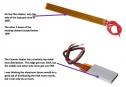 Date: 03/22/24 00:07 Re: ScaleTrains’ BNSF Frostline Reefer (WARP 6) – Meltdown Author: tmotor Heat Transfer
The idea of having an electrical heat source small enough to fit inside the shell was not looking good. I turned to an old-school Hot Plate I had stored-away. (It had come THIS close to being part of a yard sale. It’s times like these that I’m glad I kept it.) The heat source (pressed against the shell) didn’t have to be electrically powered. If a piece of metal is heated-up and then placed against the shell, in theory it will work. In Hot Water Aluminum is a good conductor of heat. In theory, if it is placed in boiling water, it will soon be at the same temperature. A pan with some water was placed on the Hot Plate, and brought to a boil. A Bar was submerged in the water. Since water is a great medium for the transfer of heat, it was removed after about 5 minutes. It was fished-out with a pair of tongs, dried on a towel, and placed on a piece of cardboard. The thermal gun showed it was around 110F. It was returned to the boiling water, left for 15 minutes, and fished-out. Same temperature readings. So being surrounded by 200F water on all sides did NOT help push the temperature any higher than 110F. Increasing the temperature of the Hot Plate would NOT increase the temperature of the water, but merely cause the water to boil-off faster. Baked Into Submission The water was drained-out of the pan. A lid was placed on the pan to keep the air surrounding the Bar as hot as possible. When the thermal gun read 200F, the Bar was removed. The thermal gun then measured the Bar at about 110F. There’s no way the temperature dropped that much in a few seconds, so it appears the thermal gun was picking up the heat from the Hot Plate as well as the Bar. To compensate, the Bar was left in the pan for 15 minutes to ensure it had enough time to come up to temp. However, the Bar still remained at 110F. Was the aluminum Bar transferring heat to the air faster than the Hot Plate could give heat? Nope. Turns out that due to the properties of aluminum, it absorbs only a percentage of the surrounding heat. (More time won’t make a difference.) A much higher temperature needs to be input before seeing a temperature rise in aluminum. This explained the temperature readings I was seeing. Unless the Hot Plate temperature was much higher, the aluminum Bar would not reach 200F. The Heat Is On An internet search for the melting point of ABS plastic found it is around 200F. I used that as the ballpark temperature to use. (Unfortunately, what I should have been looking for was the temperature when the plastic softens and is still semi-solid.) When they say melting point, they aren’t kidding! The first test with a Bar at 200F blew right thru the plastic sheet. The dial setting on the Hot Plate was then reduced to the lowest setting. To my surprise, even this low setting this was enough to soften the ABS sheet. When the Bar softens the plastic, the plastic sticks to the Bar. It can be pried away, but in doing so the plastic is pulled (sort’ like taffy) into a dome-shape. If this is immediately sandwiched between the Dies, it could be worked into the desired shape. However, if it cools before the Dies are in-place, the dome-shape hardens and the working window is closed. Trying to reheat it is a problem since the Bar can only be used if the surface to be heated is flat. If it is now dome-shaped, the Bar will create uneven contact. Since the Bar can only be used when the surface is flat, I basically would have one shot at it. Do Not Hump One property of the Evergreen sheet is it will expand when heated. This usually resulted in the surface bowing upwards, towards the Bar. This meant the center of the Bar makes good contact with the surface, but the outer edges do not. As the hump rises in the center, the Bar is pushed farther away from the other surfaces. The center is the only point of heat transfer, and the hump grows larger with time. This resulted in the center being hot enough to be manipulated, but the outer perimeter was too cold. It is possible that a pair of Bars could be clamped to the surface, one above and one below. This would (hopefully) prevent the hump from forming. My fear is the shell would need to expand someplace, so it would expand horizontally, causing the dimensions to change and twisting the shell out of shape. Blisters This expansion property of the ABS material (in the Evergreen sheet) was going to complicate the use of Dies to form the Weld Warpage. Instead of trying to compensate for this property, what if it could be “harnessed” and used to advantage? It occurred to me that the surface will form a blister when heat is applied. What if the heat could be applied in the desired pattern, and blisters formed in the shape of the Weld Warpage? :-D In theory, this could be done by using a mask having slots in it that matched the pattern needed. A heat gun could provide the heat, which would reach the shell surface through the slots. The plastic would form a series of blisters in the shape of the Weld Warpage. Instead of the entire surface needing to be pliable, only small areas would receive heat. Less heat input means less chance of twisting the shell out of shape. If this worked, it would be a Game-Changer! My preference was to apply heat only to the backside of the shell. This would reduce the chance of damaging the lettering and graphics. The backside is unpainted, so the heat does not need to penetrate paint before reaching the shell. Heating the backside would cause blisters on the backside, and presumably cause depressions on the frontside. In order to have a blister form on the frontside, would heat have to be applied from the frontside? Or, could heat from the backside be use to soften the shell and pressure from a Die be used to force the shell to bow away from the heat (vs. towards it, as is its natural tendency)? Hybrid Dies In an ideal world, the only thing on the exterior of the shell would be a layer of silicone sheet, with a Die pressing against it. All heat would be delivered from the backside. I would need to fashion a defector (to fit on the heat gun) that forces the hot air to make a sharp right-angle turn. The Dies would still be used to sandwich the shell. The Die on the backside will have slots added to its CAD geometry. Heat will pass thru those slots, and heat the backside of the shell. When a blister is formed on the backside, the frontside gets an associated depression. In order to have the opposite happen, the Die must be shaped into a dome with a slot at the apex. When heat is applied (from the backside) the shell will soften and want to bow towards the heat. However, the Die will force it to bow away from the heat. A slot-shape will be pressed into the backside for the shell, but it won’t be visible. What will show is that the shell has been forced outwards and into the cavity of the exterior Die. This will result in a smooth continuous flow of ripples on the exterior shell surface. The slots on the backside will be used for creating BOTH blisters and depressions on the exterior. In the original process with the non-slotted Dies, time needs to be taken to remove the Bar (providing heat), position the Dies, and apply clamping pressure. All the while the shell begins to cool as soon as the Bar is removed. The odds of having that consistently go well is slim. If any part of the heated area cools too quickly, the Dies are prevented from doing their work. One big advantage of the Hybrid Dies is they are already clamped in-place as the heat is being applied. While clamping pressure is being applied by the Dies, the slots allow the heat to reach the shell. The instant the shell softens, the Dies form the Weld Warpage. That’s the theory anyway. Stay tuned to see if it will actually work. Dave Edited 11 time(s). Last edit at 03/22/24 12:33 by tmotor. 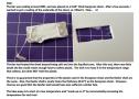 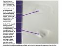 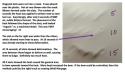 Date: 03/22/24 07:24 Re: ScaleTrains’ BNSF Frostline Reefer (WARP 6) – Meltdown Author: bigmc83 Excellent write up and conclusions. Would a heat gun with a small diameter nozzle directed inside the car achieve this?
-Sean Date: 03/22/24 09:10 Re: ScaleTrains’ BNSF Frostline Reefer (WARP 6) – Meltdown Author: tmotor Greetings Sean!
> Excellent write up and conclusions. I appreciate the words of encouragement. :-D > Would a heat > gun with a small diameter nozzle directed inside > the car achieve this? Yes, but ideally it will be able to hit all areas of the mask at once. That way the temperature to all slots will be consistent. I'm thinking of a miniature version of this duct fitting used to transition from a circular feed to a rectangular vent. Take care and God bless! Dave 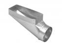 |