| Home | Open Account | Help | 378 users online |
|
Member Login
Discussion
Media SharingHostingLibrarySite Info |
Model Railroading > TCS #1619 Motherboard - Wiring problemsDate: 11/30/18 18:09 TCS #1619 Motherboard - Wiring problems Author: highballer1 Anyone else have problems deciphering where what wire goes where on the TCS 16129- lB-MB1-NC Motherboard?? The documentation is not very clear about how to connect the Truck-Track Wires onto the motherboard and for the first time in doing DCC Decoder installs, I have had some very significant issues with this motherboard.
Date: 11/30/18 22:13 Re: TCS #1619 Motherboard - Wiring problems Author: MMD Contact TCS they are very helpful.
Malcolm New Zealand Date: 12/02/18 09:39 Re: TCS #1619 Motherboard - Wiring problems Author: fbe First off you show 1619 in the subject line but 16129 in the text. Please edit out the 2 in the text.
From the tcsdcc home page search for IB-MB1-NC to find the motherboard. The result is a photo with the track connections labeled on the left end of the decoder photo. Beyond that they track wires are not labeled. The linked spec sheets do not label them either. I found an installation photo series of the motherboard in an Athearn MP-15DC model on the TCS pages and you can tell from the wire size in the photo post installation both wires from one track go next to the capacitors while both wires from the other rail go towards the open end of the decoder. This is sort of opposite of the common eack truck connection on opposite ends of the decoder. Think of it as FT LR RR RT LR RR In this case the right rail connections are toward the middle of the motherboard next to the capacitors. This might make the unit run in reverse and if it does change the connections to FT RR LR RT RR LR I hope this helps. Edited 1 time(s). Last edit at 12/02/18 10:03 by fbe. Date: 12/02/18 18:40 Re: TCS #1619 Motherboard - Wiring problems Author: WrongWayMurphy I cant stand the 21 pin arrangement, but here is the diagram nonetheless.
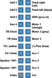 Date: 12/02/18 19:04 Re: TCS #1619 Motherboard - Wiring problems Author: fbe You can just ignore those 21 pins, they are exclusively between the decoder and the motherboard. What you need for lighting and other outputs are the Functions solder points. The long row of points about 1/3 the way in from the right are numbered sequentially from the bottom to the top though some outputs are singularly found at other locations on the motherboard. You will need to get to the esu decoder instructions to find out what the Fn outputs are for.
I would send you the photo of the motherboard but it is a pdf download and I cannot link out to it. Date: 12/02/18 19:36 Re: TCS #1619 Motherboard - Wiring problems Author: fbe This shows the motherboard connections though track connections are poorly defined.
I think you need to ignore the +12v and blue lighting output if you are using led lights with an esu decoder. Work that out with tcs or esu unless someone comes up with the answer here. Edited 1 time(s). Last edit at 12/02/18 19:51 by fbe. Date: 12/06/18 08:44 Re: TCS #1619 Motherboard - Wiring problems Author: fbe So how did we get into this predicament? What locomotive is this going to be installed in? What was in it when it left the factory? Why did you chose a TCS motherboard if you were going to use an ESU decoder.
I agree the instructions for the track and motor connections are just cryptic. The lighting connections in the diagram are useful. Once you get the F0 light connected you will be able to set and reset the motor polarity and track connections so the engine runs forward when the front headlight is turned. I would wire the front and rear headlights up first since they are marked. Then I would hook up one truck. Put the unit on the track with DCC and turn on the headlight. Change direction to see if the proper light comes on. If not swap the truck wires. Once the direction of the lights is right add the second truck and solder the wires. Now connect the motor wires. If it moves forward with the throttle then the polarity is correct and you can solder the motor connections. If the throttle is FWD and the front headlight is on but the loco moves in reverse then you need to swap the motor connections to make it right. The speaker connections will work either way. Once this is all done I would get out some paint and spot the right rail connection and the wire from the truck with a spot of red paint. I would probably mark the connection for the left track with black paint. Then I would use orange and grey paint to mark the motor wires and the motherboard connections. If the motor does not already have coded wires you will have to connect them to a motherboard with know connections until you get both motors turning the same direction. Then paint the wires accordingly or change the wires to orange and grey or red and black. Spot mark the motherboard connections to match. Please let us know how this works or what TCS tells you. Edited 1 time(s). Last edit at 12/06/18 09:07 by fbe. Date: 12/13/18 11:30 Re: TCS #1619 Motherboard - Wiring problems Author: fbe It has been about 2 weeks since your request for help and we haven't heard back about how the project is coming along. Any progress yet?
|