| Home | Open Account | Help | 378 users online |
|
Member Login
Discussion
Media SharingHostingLibrarySite Info |
Steam & Excursion > Westinghouse A-1 Brake EquipmentDate: 11/19/14 10:44 Westinghouse A-1 Brake Equipment Author: LarryDoyle In another thread hogheaded asked, "First, I'm not sure that I have heard of the A1 straight/auto air. I'm only familiar with the term's modern use as the A-1 Charging/Cut-Off Pilot Valve. How did the A1 function in relation to auto/straight air?
http://www.trainorders.com/discussion/read.php?10,3580158 The locomotive system of 1887 as the Automatic Air Brake featured a single engineers control valve, the D-8. It had Release, Running, Lap, Service, and Emergency positions and functioned much as the H-6 valve used on a 6-ET brake would, later. Except, there was no distributing valve, and the tender brakes were applied by a triple valve, the same as any car in the train. Engine driver brakes were either non-existant or were controlled by the tenders triple. This system is illustrated below. In 1896 the Combined Straight Air and Automatic Brake featuring an added separate straight air brake for control of the locomotive and tender. An improved engineers valve (The D-5, E-6, or F-6 were all the same valve but changed numbers in newer catalogs) featured an improved feed valve. Also added was an engineers independent control valve, shown below, which separately controlled the locomotive and tender brakes. Optionally, a double check valve could tie the to systems together so that engine brakes could be applied and released by either system. "Bailing" as not an option, as the double check valve is "designed to connect automatically the brake cylinder(s) to either the tripe valve of the automatic brake or the straight air brake valve and thus prevent air from passing out of the exhaust port of one system while the other is being oeperated." This came to be called the A-1. The 5-ET was introduced about 1905 with a G-5 Engineers brake valve, which added a Holding position for the engineers use. The 5-ET could be set up as a straight air automatic, or could replace the straight air parts with an S-6 independent brake valve controlling a distributing valve. In 1906 the 6-ET replaced the 5-ET, with no new functionality, but with improved components, H-6 control valve and fewer parts, with more easily maintained bolt-on portions. This became the defacto standard for the next 51 years! -John Edited 2 time(s). Last edit at 11/19/14 12:58 by LarryDoyle. 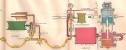 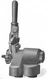 Date: 11/19/14 14:01 Re: Westinghouse A-1 Brake Equipment Author: hogheaded >Also added was an engineers independent control valve, shown below, which separately controlled the locomotive and tender brakes.
OK, now I get that A1 was just sort of the vernacular for those pre #5 systems. In the air brake chart, I don't see the independent, just the automatic controlling the tender/train brakes. So let me get this straight: the independent, when there was one, would have been a separate system that only controlled the engine brakes, and that when that "double check valve" was employed, the automatic could be used to control the engine/tender/train brakes, with no ability to bail? If the engine was running light, therefore, the engineer would employ the automatic so as to have both engine and tender braking? Coincidentally, I have a 3' long framed copy of the same basic chart dated May, 1902 hanging on the wall of my "Engineer's Relief Lounge". It came from the Locomotive Fireman's Magazine and cost a princely 25¢ (in 1902). It's pretty! I'll take a 26-E any day! Thanks for your explanation, John! -E.O. 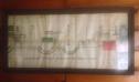 Date: 11/19/14 19:04 Re: Westinghouse A-1 Brake Equipment Author: jbbane Someone can correct me as I don't have my books where I am at, so may recall this wrong. The D8 automatic brake valve was somewhat more primitive in function as it did not use a feed valve, than the F6 and G6 valves. The low side of the duplex governor on the air compressor was connected directly to the train line, so with the brake valve in running position, main reservoir pressure and train line pressure were one and the same. When a brake pipe reduction was made and the D8 put in lap, the high side of the duplex compressor governor was connected to main reservoir air pressure. This allowed a build up of main reservoir air to assist with releasing the triple valves and recharging the reservoirs on the cars when it came time to move the valve to run. I imagine this system was pretty limited as to train length and use where cycle braking was required. If the added volume stored in the main reservoir when in lap and the high side governor operative, was insufficient to mostly recharge the reservoirs on the cars when the D8 was placed in run, full recharge could take a longer time than later systems with excess air always maintained in the main res. I would have to wonder if one might have a problem with a longer train with this scheme having the front triples sometimes set again after release as air press. could drop near the front of the train once the initial boost of excess air in the main res. was gone and the rear of the train still taking a lot of air to recharge. I have never seen this scheme except in books, though I have worked with a steam locomotive with a G6 and feed valve but with the duplex governor connected like the D8 scheme. It is a little problematic at times, though one can learn to work with it.
Date: 11/20/14 05:26 Re: Westinghouse A-1 Brake Equipment Author: hogheaded >It is a little problematic at times, though one can learn to work with it.
Well, don't you think that this is one of the things that defines the engineers' craft - the ability to work with what you've got? Thanks for the post! -E.O. Date: 11/20/14 07:48 Re: Westinghouse A-1 Brake Equipment Author: LarryDoyle jbbane Wrote:
------------------------------------------------------- > Someone can correct me as I don't have my books > where I am at, so may recall this wrong. The D8 > automatic brake valve was somewhat more primitive > in function as it did not use a feed valve, than > the F6 and G6 valves. The drawing clearly shows the D-8 valve marked "Engineers Brake Valve With Feed Valve Attachment." There would be no purpose served by the "Release" position of the valve, if there were no Feed Valve, as "Release" and "Running" would function identically. The low side of the duplex > governor on the air compressor was connected > directly to the train line, so with the brake > valve in running position, main reservoir pressure > and train line pressure were one and the same. The Duplex Governor had not yet evolved. > When a brake pipe reduction was made and the D8 > put in lap, the high side of the duplex compressor > governor was connected to main reservoir air > pressure. This allowed a build up of main > reservoir air to assist with releasing the triple > valves and recharging the reservoirs on the cars > when it came time to move the valve to run. I > imagine this system was pretty limited as to train > length and use where cycle braking was required. > If the added volume stored in the main reservoir > when in lap and the high side governor operative, > was insufficient to mostly recharge the reservoirs > on the cars when the D8 was placed in run, full > recharge could take a longer time than later > systems with excess air always maintained in the > main res. I would have to wonder if one might have > a problem with a longer train with this scheme > having the front triples sometimes set again after > release as air press. could drop near the front of > the train once the initial boost of excess air in > the main res. was gone and the rear of the train > still taking a lot of air to recharge. I have > never seen this scheme except in books, though I > have worked with a steam locomotive with a G6 and > feed valve but with the duplex governor connected > like the D8 scheme. It is a little problematic at > times, though one can learn to work with it. Yes, the brake was slow in operation - as were the type H triples on the cars. With air brakes, passenger trains were limited to about 12 cars, freight trains about 18 or 20. Yet, longer trains were run, about 40 cars or so being the maximum. Locomotives were smaller then, too, of course. How did they do this? "Part Air" trains. Brakes were cut in only on the front portion of the train! As hogheaded said, it's part of the skill of the craft. The Type K freight car brake, and its passenger equivalent the Type L introduced right after the turn of the century, and the 5-ET and 6-ET speeded up propagation, allowing train lengths to increase with brakes on 40 cars or so. But of course, railroads continued to push this, and continued to run part air trains up 'till after the AB brake valves were introduced, in 1933, which were reliable for 150 cars. Operating rulebooks include a few universal hand and lantern signals (and, every railroad and every yard had additional signals of part of their local signal language and dialect.) One of the seven universal signals is: "A train-parted signal is given by swinging the hand, flag, or lamp vertically in a circle at arm's length across the track. The engineman should acknowledge this by sounding the train parted whistle signal, and if the air does not stop the train, he should keep the forward portion of the train in motion until the rear portion is stopped." [Standard Code of Train Rules of the American Railroad Association.] The whistle response was three long. The skill of the craft, indeed. -John Edited 2 time(s). Last edit at 11/20/14 10:50 by LarryDoyle. 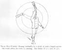 Date: 11/20/14 13:34 Re: Westinghouse A-1 Brake Equipment Author: hogheaded >But of course, railroads continued to push this, and continued to run part air trains up 'till after the AB brake valves were introduced, in 1933, which were reliable for 150 cars.
>Operating rulebooks include a few universal hand and lantern signals (and, every railroad and every yard had additional signals of part of their local signal language and dialect.) One of the seven universal signals is: "A train-parted signal is given by swinging the hand, flag, or lamp vertically in a circle at arm's length across the track. The engineman should acknowledge this by sounding the train parted whistle signal, and if the air does not stop the train, he should keep the forward portion of the train in motion until the rear portion is stopped."< This is quite a revelation to me, that part air trains were legal until 1933. Amazing! I aways thought that the "train parted" signal was one of those rulebook artifacts left over from the 19th Century, not the first third (again: Amazing!) of the Twentieth. Another reason why head end crews bought the farm more often than any other rails. Thanks John! -E.O. Date: 11/20/14 14:41 Re: Westinghouse A-1 Brake Equipment Author: LarryDoyle hogheaded Wrote:
------------------------------------------------------- > > This is quite a revelation to me, that part air > trains were legal until 1933. Amazing! It wasn't. It was supposed to disappear, and all trains were supposed to have 85% working brakes from the time the K brake was introduced. But the practice continued for some time. I aways > thought that the "train parted" signal was one of > those rulebook artifacts left over from the 19th > Century, not the first third (again: Amazing!) of > the Twentieth. Another reason why head end crews > bought the farm more often than any other rails. The other alternative was to run your 100 car train of K brakes, with all cars cut in but applying, releasing, and recharging slowly. Also hazardous for head-end crews. D, E, F, G, and H locomotive brake valves all had a Release position, to be used judiciously by the engineer to put air into the brake pipe at main reservoir pressure in order to achieve quicker release. The risk in its mis-use is that a train could be overcharged. Charging the train to MR pressure of 110 psi then making a full service application gives you an equalizing pressure of about 80 psi. With your feed valve set at 80 or less (typical until about 1950) you would be unable to release the brakes! After the AB valve became near universal on the train cars, railroads started welding blocks onto the H-6 valves of the 6-ET and 14-xx systems to prevent use of this feature, and Westinghouse chose to not make it an option on the 26-C. > > Thanks John! > > -E.O. Edited 1 time(s). Last edit at 11/21/14 08:30 by LarryDoyle. Date: 11/20/14 17:14 Re: Westinghouse A-1 Brake Equipment Author: jbbane This is a great thread covering some of the early brake system stuff that rarely gets talked about with little opportunity for most of us to learn about it. I was afraid I was on shaky ground on my comments on the D8. Since my earlier post and the correction by LarryDoyle I pulled out a 1901 Westinghouse book and find that neither of us had it quite right at least at the time this book came out. The D8 described by Westinghouse did not have a feed valve. It had an excess pressure valve built into the body of the brake valve. The air pump governor (not a duplex governor) was connected normally to train line pressure through a port in the brake valve with gov. press. set for 70lbs which was std. train line press. When the brake valve was placed in the running position, main res. pressure has to pass through the excess press. valve to reach the governor. The spring in the excess press valve required 20 additional pounds to cause it to open, thus causing the air pump to continue to operate bringing main res. press. to 90. Other aspects appear similar to F6 and G6. My description of the governor piping arrangement on a locomotive I am familiar with is WHEccles #3 at Sumpter Valley. I seem to recall finding a reference to having the train line connected to one side of the duplex governor in some old manual, but not sure where. About the only advantage I can think of is it makes a faulty feed valve that tends to overcharge the train line less of an issue. I have wanted to try connecting it in the conventional manner, but time has never been available for experimentation.
Date: 11/21/14 06:26 Re: Westinghouse A-1 Brake Equipment Author: hogheaded >The other alternative was to run your 100 car train of K brakes, with all cars cut in but applying, releasing, and recharging slowly. Also hazardous for head-end crews.
Or, the RR could have run shorter trains, which would have been less prone to brake-related delays, not to mention accidents, but this is apostasy. >The risk in its mis-use is that a train could be overcharged. Charging the train to MRE pressure of 110 psi then making a full service application gives you an equalizing pressure of about 80 psi. With your feed valve set at 80 or less (typical until about 1950) you would be unable to release the brakes!< I understand what you mean, but illegally, an overcharge can be your (fickle) friend when picking-up cars on a downhill grade. After cutting away from the train and latching onto your pickup, you crank-up the feed valve to about 110. When you double back to the train, you crank the feed valve back to 90, which sets-up the pickup and releases the rest of the train. This way you don't have to "waste time" by applying and releasing handbrakes on the train. Then, the brakes on the pickup act as retainers all the way down the hill, giving you more flexibility with the air and dynamics. A hoghead, who seemingly spent more time fired than marked-up, showed me this trick once on an eastbound at Upton siding, near Mt. Shasta. By the time we got to Dunsmuir the head ten cars, our pickup, were nearly on fire (note: in retainer days, trains were required to stop about mid-way for heat radiation) and I was worried that J.J. Plank, the Trainmaster/Ruler of Dunsmuir, would see the smoke plume as we went by the depot. I think that my engineer applied and released the brakes only about three or four times before we turned-over the train to a Roseville crew, so those head cars still had a significant overcharge (what was the rule of thumb - overcharge reduced by 2 or 2.5 psi per set & release? - I forget). My hoghead never mentioned what he had done to our relief, of course, so I can imagine the troubles they had further down the canyon. Instructive, but otherwise, lazy and dumb. From what I understand of railroading since I retired, you couldn't get away with it today anyway, because today's road foremen would rather read tapes than girlie magazines. -E.O. Date: 11/21/14 08:38 Re: Westinghouse A-1 Brake Equipment Author: LarryDoyle Feedvalving is also prohibited.
Date: 11/21/14 11:59 Re: Westinghouse A-1 Brake Equipment Author: hogheaded LarryDoyle Wrote:
------------------------------------------------------- > Feedvalving is also prohibited. I doubt that *any* engineer ever used feed valve braking to descend a hill when the pressure maintaining was kaput (-: -E.O. Date: 11/21/14 12:35 Re: Westinghouse A-1 Brake Equipment Author: flash34 Oh heavens no.
Posted from iPhone Date: 11/21/14 12:48 Re: Westinghouse A-1 Brake Equipment Author: LarryDoyle Or, as the oldtime engineer trained on 6-ET said when he was first shown a 26C valve, "Pressure maintaining? We don't need no pressure maintaining. Just ride the hump!"
Who, out there, wants to explain that one to the newbies? -John Date: 11/21/14 13:14 Re: Westinghouse A-1 Brake Equipment Author: flash34 That seemed to me like a lot sketchier method than feed-valving, which works very well (I've heard...).
Posted from iPhone Date: 11/21/14 21:31 Re: Westinghouse A-1 Brake Equipment Author: EtoinShrdlu A few quick comments:
Brake valve history: 1868 Three-Way Cock (straight-air, adapted to automatic air in 1876) 1882 Engineer's Brake Valve, Plate A-11 (automatic air, self-lapping; self-lapping mechanism rather primitive and prone to problems) 1886 Engineer's Brake and Equalizing Discharge Valve, Plate B-12 (non self-lapping; self-lapping automatic brake valves not put in production until the 26-L system of the late 1950s) 1887 Engineer's Brake and Equalizing Discharge Valve, Plate C-7 1889 Engineer's Brake and Equalizing Discharge Valve, Plate D-8 1892 Engineer's Brake and Equalizing Discharge Valve, with Feed Valve Attachment Plate E-6 (first external feed valve) 1894? Engineer's Brake and Equalizing Discharge Valve, with Feed Valve Attachment Plate F-6 1898? Engineer's Brake and Equalizing Discharge Valve, with Feed Valve Attachment Plate G-6 (the only difference between an F-6 and G-6 brake valve is the attached feed valve) Source: original WABCo part catalogues, dated 1882, 1890, 1894, and 1900 and "Mitchell's Models", International Correspondence School, 1901 C-7 and D-8 were similar in having an internal, primitive "feed valve". The "Schedule A-1" system was automatic only, using a G-6; no straight air. This was followed by SWA/SWB, "Straight With Automatic" ("B" being for passenger service), which used the F-6/G-6 automatic brake valve and the S-3 pictured earlier in this thread (vertically oriented handle), and finally the ET series. 5-ET used an SF independent brake valve. Quick action was introduced in 1887 with the H triple valve. K and L triples were introduced in 1906, bringing quick service. Quick service is what speeded up the application, not the engineer's brake valves, but only in the initial one provided it wasn't greater than about 6 psi. The K also introduced retarded release and retarded recharge, which along with the "release" position on the H-6 brake valve helped make brake pipe pressure increase at the rear of the train during a release happen more contemporaneous with the front part. What really obsoleted the Release position on the automatic brake valves was the accelerated recharge feature of AB (uses air from the Emergency reservoir to help recharge the Aux). Date: 11/23/14 12:35 Re: Westinghouse A-1 Brake Equipment Author: hogheaded >A few quick comments:
>Brake valve history: Very instructive! It's so good that I shall file this info away so that I can claim that it is my own at some point. So, since you are way ahead of me on mechanicals, I ask you to explain this work report left on an engine by the late and beloved Engineer Pat West. I can't remember it exactly, but it went something like this: When I turned the red thing one way, the black thing went round and round OK, but it made a funny noise. When I turned it the other way, the yellow thing got stuck, but it did not make any noise. Please fix! -E.O. Date: 11/23/14 17:29 Re: Westinghouse A-1 Brake Equipment Author: EtoinShrdlu Could it have had anything to do with dynamatic brakes?
Date: 11/24/14 02:38 Re: Westinghouse A-1 Brake Equipment Author: Jim700 LarryDoyle Wrote:
------------------------------------------------------- > Or, as the oldtime engineer trained on 6-ET said > when he was first shown a 26C valve, "Pressure > maintaining? We don't need no pressure > maintaining. Just ride the hump!" flashe34 Wrote: ------------------------------------------------------- > That seemed to me like a lot sketchier method than > feed-valving, which works very well (I've heard...). John, I suspect that the "hump" to which you referred is another name for the method that the old heads teaching me called the "bridge". I used it a lot on the Tonquin Hill and Cornelius Pass on the Oregon Electric Railway. I generally had good luck with it unless the gauge needle displayed "sticky" movement which prevented the needed observing of minute pressure changes to successfully brake in that manner. I'd also agree with Scott that it was a sketchier method of "manual" pressure maintaining braking than feed-valving (none of us would have ever done that, would we ?!?) but if you paid close attention to the needle it was easier than almost standing on your head to reach the feed valve nearly buried under the dashboard of an Alco FA equipped with a 24-RL brake stand. The first pressure maintaining valves on my road showed up on the Century Series Alcos. Date: 11/24/14 05:12 Re: Westinghouse A-1 Brake Equipment Author: flash34 True Jim, the feed valves on some engines are/were much more accessible than others.
Date: 11/24/14 07:10 Re: Westinghouse A-1 Brake Equipment Author: LarryDoyle That's right, Jim.
After taking your reduction for a brake application, instead of moving the H-6 brake valves handle from "Service" to "Lap", you'd just move it onto the "hump" the separates those two positions on the detent quadrant. Set it so that it just allowed enough leakage into the brake pipe to compensate for brake pipe leakage. Keeping one eye on the track and one eye on the brake pipe pressure gauge, if you saw a change of 1/2 psi in the brake pipe you'd just tap the handle with your knuckle to move it just enough to raise or decrease the valves leakage appropriate to compensate. A manually operated maintaining brake valve, for precision train driving. -John |